Method for constructing reservoir dam

A technology for reservoirs and dams, applied in dams, barrages, weirs, etc., can solve problems such as uncoordinated deformation and force, dam body stability and deformation, and inability to prevent seepage layers, etc., to ensure dam body stability and reduce The effect of uneven deformation of the dam

Inactive Publication Date: 2014-01-22
POWERCHINA ZHONGNAN ENG
View PDF4 Cites 2 Cited by
  • Summary
  • Abstract
  • Description
  • Claims
  • Application Information

AI Technical Summary

Problems solved by technology

However, using this method to build a dam on a foundation with a W-shaped cross section (the middle of the W represents a mountain ridge, and the bottom of the W represents two ravines) with a longitudinal slope greater than 17° is extremely unfavorable to the stability and deformation of the dam.
The existing technology usually adopts to excavate the middle mountain ridge to avoid the influence of the transverse "W" shape on the uneven deformation of the dam body along the axis of the dam, and then fill the dam body. The top molding area and the bottom of the dam body are not distinguished when filling the dam body The disadvantage of this method is that the investment in excavation and filling is large
In addition, in the prior art, the height of the downstream side slope of the earth-rock dam is reduced by building a gravity dam at a suitable position on the downstream side slope, and the height of the dam on the foundation with a longitudinal foundation slope greater than 17° is reduced. The disadvantage is that the dam type is a gravity dam and an earth-rock dam Mixed dam type, uncoordinated deformation and stress, and heavy gravity dam investment
The backfill gravel layer on the reservoir side of the above two dams does not have a connecting plate, so that the dam body face plate is directly connected to the geomembrane at the bottom of the reservoir, and there is no transitional connecting section in the middle, which cannot form a stable anti-seepage well. Floor

Method used


Image

  • Method for constructing reservoir dam
  • Method for constructing reservoir dam

Examples


Embodiment 1

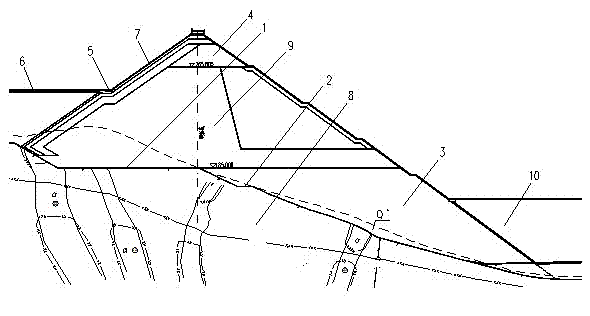
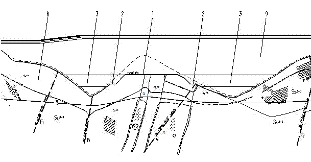
[0024] see figure 1 and figure 2 . This embodiment relies on the main dam project of the upper reservoir of the Liyang Pumped Storage Power Station. The main dam of the Upper Reservoir is a reinforced concrete face rockfill dam with a crest elevation of 295.00m, a crest width of 10m, a maximum dam height of 165.00m (at the dam axis), and a crest length of 1113.20m. The surface-to-slope ratio is 1:1.45. The cross-section of the dam foundation 8 is W-shaped, the middle of the W represents a mountain ridge, and the bottom of the W represents two ravines; the longitudinal slope of the foundation is greater than 17°.

[0025] (1) Cut the raised part of the mountain ridge into a platform 1 with a width of about 110m and a height of about 30m; excavate a horizontal platform 2 with a width of about 10m along the longitudinal slope of the foundation.

[0026] (2) The dam body 9 is filled on the dam foundation treated in step (1). During the dam construction process, the bottom and...


PUM


Abstract

The invention discloses a method for constructing a reservoir dam. The cross section of a dam foundation is W-shaped, the middle of the W-shaped cross section of the dam foundation represents mountain ridges, and the bottom of the W-shaped cross section of the dam foundation represents two valleys; the longitudinal slope of the foundation is larger than 17 degrees. The method includes cutting protruded positions of the mountain ridges to form platforms, digging a plurality of horizontal steps along a longitudinal slope surface of the foundation, and setting a bottom modulus increasing area, a top modulus increasing area and the like on a dam body to reduce uneven deformation of the dam body; setting a back pressure platform at a dam toe of the dam body and performing double-standard control on the pouring time of a face plate of the dam body to reduce adverse impact of deformation of the dam body on the impervious face plate. The method has the advantage that uneven deformation of the dam body is greatly reduced by the aid of measures such as improving a topographical condition of the dam foundation, reasonably partitioning the dam body, filling residues at the dam toe to form the back pressure platform and reasonably preserving excessive sedimentation height and sedimentation cycle, so that the stability of the dam body can be guaranteed.

Description

technical field [0001] The invention belongs to the technical field of dam building, and in particular relates to a dam building method for a reservoir dam. Background technique [0002] The upper reservoir of the pumped storage power station is usually arranged in the depression on the top of the mountain, and there will be a problem that the dam needs to be built on the foundation of two or more valleys with steep longitudinal slopes. According to the characteristics of the excavated materials of the existing dam body, the dam is divided into cushion layer area, transition area, rockfill area, upper part of the downstream rockfill area (dry area), and drainage layer at the bottom of the ditch. Fill directly on the foundation. However, using this method to build a dam on a foundation with a W-shaped cross section (the middle of the W represents a mountain ridge, and the bottom of the W represents two ravines) with a longitudinal slope greater than 17° is extremely detrime...

Claims


Application Information

Patent Timeline
Patent Type & Authority Applications(China)
IPC IPC(8): E02B7/06
Inventor 宁永升冯树荣陈宁李国权刘纯
Owner POWERCHINA ZHONGNAN ENG
Why Eureka
Try Eureka