Method and mechanical load bearing fixed chain type mechanism for generating auxiliary valve lifting curve of engine
A mechanical bearing and engine technology, applied in engine components, engine control, machine/engine, etc., can solve the problems of large inertia of the braking system, increase the volume and weight, reduce hydraulic flexibility, etc., to reduce costs, reduce requirements, The effect of simplifying the design
- Summary
- Abstract
- Description
- Claims
- Application Information
AI Technical Summary
Problems solved by technology
Method used
Image
Examples
Embodiment 1
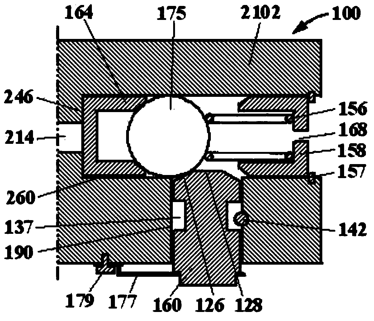
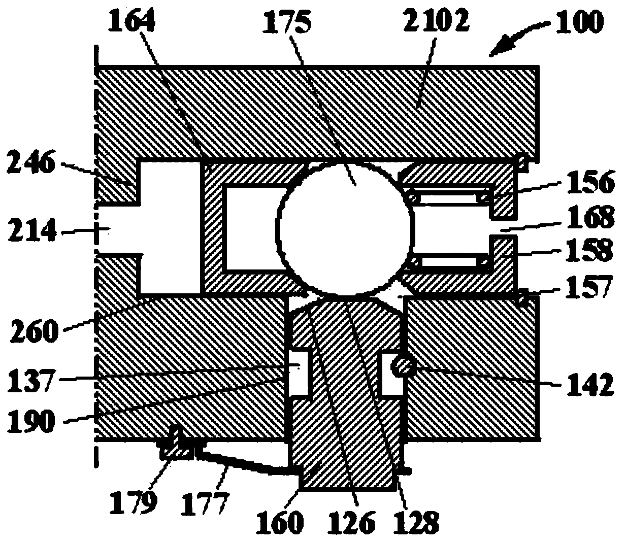
[0042] Such as figure 1 and figure 2 As shown, the fixed chain type engine brake device 100 of the present invention is composed of a brake box 2102, a driving mechanism and a braking mechanism. Intersecting vertical blind holes 190 and horizontal blind holes 260 are provided in the brake box 2102. The driving mechanism includes a driving piston 164 and a rolling ball 175. The driving piston 164 forms a fluid seal with the horizontal blind hole 260. One end of the driving piston Contact with the rolling ball to form cooperation; the braking mechanism includes a braking plunger 160 . The driving piston 164 and the rolling ball 175 are located in the horizontal blind hole 260 of the brake housing 2102, usually pushed to the left by the return spring 156, and rest on the end face 246 of the piston hole 260, as figure 1 shown. One end of the return spring 156 is located on the rolling ball 175 of the drive mechanism, and the other end is located on the spring seat 158, the spr...
Embodiment 2
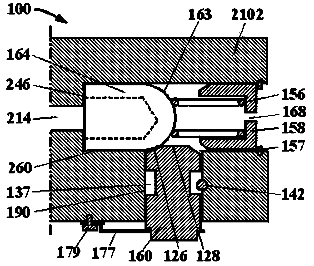
[0047] Such as image 3 and Figure 4 As shown, this embodiment is an improvement on the basis of Embodiment 1, specifically, the driving piston 164 and the rolling ball 175 in Embodiment 1 are integrated into one. The left part of the driving piston 164 is a guiding and sealing piston, and the driving surface of the right part is a spherical surface 163 (also may be a conical surface, etc.).
Embodiment 3
[0049] Such as Figure 5 and Figure 6 As shown, this embodiment is also an improvement on the basis of Embodiment 1. Compared with Embodiment 1, this embodiment cancels the driving piston, increases the return piston 162, and forms a fluid seal with the horizontal blind hole 260, and the return piston 162 is provided with decompression and discharge holes 122 and 168 (also can be a tapered combined hole). The return piston 162 is combined with the return spring 156, and the return spring 156 leans against the return piston 162 on the rolling ball 175 to press the decompression hole 122 to ensure that the rolling ball 175 is always close to the return piston 162.
[0050] The working process of this embodiment is: when the engine needs to start from the normal working state (such as Figure 5 shown) to transition to engine braking state (as shown in Figure 6 As shown), the engine brake control mechanism (not shown in the figure) opens the oil supply, and the engine oil flo...
PUM
 Abstract
Description
Claims
Application Information
 - R&D
- Intellectual Property
- Life Sciences
- Materials
- Tech Scout
- Unparalleled Data Quality
- Higher Quality Content
- 60% Fewer Hallucinations
Browse by: Latest US Patents, China's latest patents, Technical Efficacy Thesaurus, Application Domain, Technology Topic, Popular Technical Reports.
© 2025 PatSnap. All rights reserved.Legal|Privacy policy|Modern Slavery Act Transparency Statement|Sitemap|About US| Contact US: help@patsnap.com


