Guide oil injection device of steel wire rope of haulage winch

An oil injection device and wire rope technology, which is applied in hoisting devices, engine components, engine lubrication, etc., can solve problems such as fast wear of wire ropes, contamination of lubricating oil, and corrosion of wire ropes, so as to prevent rust and winding deviation, and ensure safe transportation The effect of improving and prolonging the service life

Inactive Publication Date: 2014-01-22
枣庄矿业(集团)有限责任公司柴里煤矿
View PDF7 Cites 6 Cited by
  • Summary
  • Abstract
  • Description
  • Claims
  • Application Information

AI Technical Summary

Problems solved by technology

Due to the frequent use of the transport winch in the underground inclined lane, long running time, poor working environment conditions and humid air, it is easy to cause corrosion of the steel wire rope; also because the floor of the roadway is undulating, the center line of the track is not perpendicular to the center of the drum shaft of the transport winch, resulting in the wear of the wire rope Faster, and there may even be accidents where the wire rope deviates and "climbs" and breaks off the sharp edge of the winch drum to cut the wire rope; therefore, generally, the safe service life of each wire rope is only about 1-2 months
In order to prolong the service life of the steel wire rope, it is necessary to apply oil to the steel wire rope. Due to the limitation of the original technical conditions, the oiling operation is generally carried out manually. In this way, it is not only difficult to control the amount of oil, the application is uneven, and the oil is easy to drip on the bottom plate, causing Site contamination and lubricant waste

Method used


Image

  • Guide oil injection device of steel wire rope of haulage winch
  • Guide oil injection device of steel wire rope of haulage winch
  • Guide oil injection device of steel wire rope of haulage winch

Examples


Embodiment Construction

[0024] The present invention will be further described below in conjunction with accompanying drawing and specific embodiment:

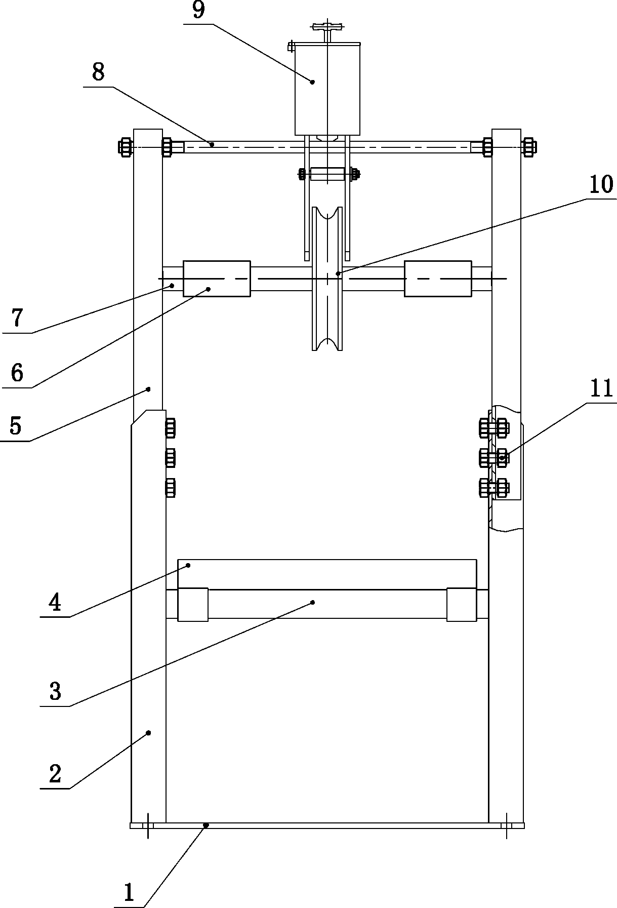
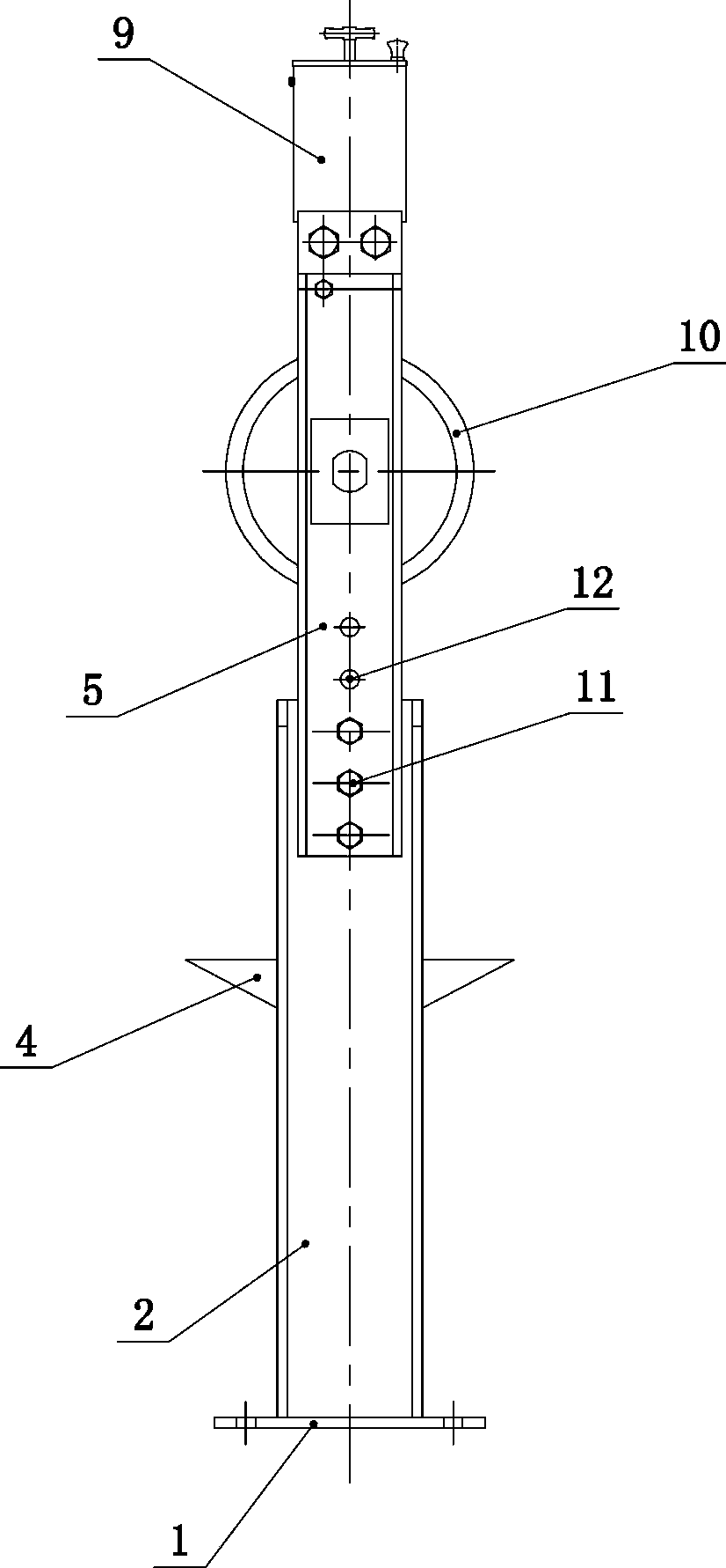
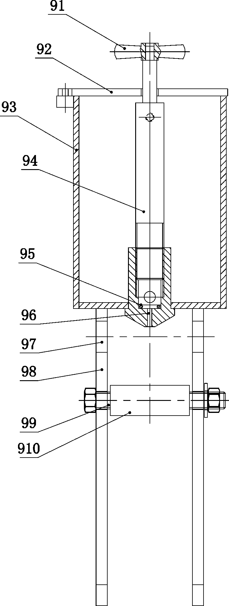
[0025] A transport winch wire rope guide oiling device, such as Figure 1 to Figure 4 As shown, it includes the underframe. The underframe includes upright columns 2 correspondingly arranged on the left and right. The upright column 2 is telescopically connected with telescopic station beams 5. The telescopic station beams 5 are connected with wheel shafts 7 and guide sliders 8. The guide sliders 8 are located on the wheel axles. 7 above, on the wheel shaft 7, slide left and right to be connected with guide swimming sheave 10, on guide slide bar 8, slide left and right and be connected with oiler 9; Oiler 9 comprises oil storage tank 93, and oil storage tank 93 has the opening upward, storage An upper cover is connected to the opening of the oil tank 93, and an oil filling valve is connected to the upper cover for relative rotation. The oil filling v...


PUM


Abstract

Disclosed is a guide oil injection device of a steel wire rope of a haulage winch. The guide oil injection device comprises a base frame, wherein the base frame comprises stand columns, and the stand columns are correspondingly arranged in a left-and-right mode. Stretchy standing beams are connected with the stand columns in a vertical-stretchy mode, an axle and guide sliding rods are connected between the stretchy standing beams, the guide sliding rods are arranged above the axle, a guide moving rope wheel is in sliding connection to the axle in a left-and-right mode, and an oil injection device is in sliding connection with the guide sliding rods in a left-and-right mode. The oil injection device comprises an oil storage tank, an upward opening is formed in the oil storage tank, the opening in the oil storage tank is connected with an upper cover, an oil injection valve is connected inside the upper cover in a relative-rotating mode, the oil injection valve comprises a valve core, the bottom wall of the oil storage tank is in seal connection with an oil injection nozzle, the oil injection nozzle is provided with an oil injection hole, the lower end of the valve core corresponds to the oil injection hole, the left side and the right side of the lower face of the bottom wall of the oil storage tank are correspondingly and fixedly connected with clamping plates, the guide moving rope wheel is arranged between the left clamping plate and the right clamping plate, the oil injection hole is formed above the guide moving rope wheel, guide sliding rod holes are formed in the clamping plates, the guide sliding rods penetrate through the guide sliding rod holes, a beam is fixedly connected between the stand columns, and an oil collection disc is arranged on the beam.

Description

technical field [0001] The invention relates to a mining device, in particular to a wire rope guiding oiling device for a transport winch. Background technique [0002] The winch is the main method of transportation in the inclined roadway of the coal mine, and the safety and reliability of the transportation winch is directly related to the safe production of the coal mine. Due to the frequent use of the transport winch in the underground inclined lane, long running time, poor working environment conditions and humid air, it is easy to cause corrosion of the steel wire rope; also because the floor of the roadway is undulating, the center line of the track is not perpendicular to the center of the drum shaft of the transport winch, resulting in the wear of the wire rope Faster, and even accidents where the steel wire rope deviates and "climbs" and breaks off the sharp edge of the winch drum to cut the steel wire rope; therefore, the safe service life of each steel wire rope ...

Claims


Application Information

Patent Timeline
Patent Type & Authority Applications(China)
IPC IPC(8): F16N11/02B66D1/36
Inventor 徐永和赵恒国王义何伟黄传存高壮利刘瑞存李华兴王军魏凤友
Owner 枣庄矿业(集团)有限责任公司柴里煤矿
Why Eureka
Try Eureka