Design of flight path planning algorithm based on fault grid

A track planning and grid division technology, which is applied in navigation calculation tools, navigation, surveying and mapping and navigation, etc., can solve the problems of easy to fall into local search, high computational complexity of UAV track planning, and difficulty in real-time track planning, etc. question

Active Publication Date: 2016-06-01
CHINA AEROSPACE TIMES ELECTRONICS CORP
View PDF5 Cites 2 Cited by
  • Summary
  • Abstract
  • Description
  • Claims
  • Application Information

AI Technical Summary

Problems solved by technology

[0012] The purpose of the present invention is to solve the problems of unmanned aerial vehicle track planning calculation complexity is too large, real-time track planning is difficult, etc., and it is easy to fall into local search, and a track planning method based on environment grid division is proposed

Method used


Image

  • Design of flight path planning algorithm based on fault grid
  • Design of flight path planning algorithm based on fault grid
  • Design of flight path planning algorithm based on fault grid

Examples


Embodiment Construction

[0022] The following part will describe in detail the specific implementation manner of the present invention in conjunction with accompanying drawing of description:

[0023] Step 1. Initialize

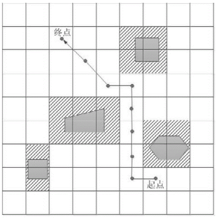
[0024] Load the map and elevation data, determine the map range corresponding to the flight area and divide the unit length of length, width and height, so as to determine the size of the three-dimensional space to be established n 1 , n 2 and n 3 . Load various radar, gunfire threat data. Given origin and destination information.

[0025] Step 2. Environment Modeling

[0026] The three-dimensional space of UAV flight environment planning is expressed as the geometric space area {(x,y,z)|0≤x≤n 1 ,0≤y≤n 2 ,0≤z≤n 3}. When performing two-dimensional modeling, the UAV flight environment is horizontally divided into two-dimensional n 1 ×n 2 Grid (Mesh, denoted as M 2 ). by n 3 M 2 Stack up according to the unit distance, and connect the corresponding nodes to form a three-d...


PUM


Abstract

The invention provides a grid division sailing planning method based on an environment, and the method is used for unmanned aircraft sailing planning. According to the method, the flying coverage area is divided into two-dimensional grids and / or three-dimensional grids, topographical obstacles and various threats are modeled into failure nodes in grids, the planning method comprises the steps of initialization, environment modeling and node labeling, recognition of minimum communication failure blocks and construction of boundaries thereof, and computation of shortest route. The complexity of the sailing planning method and the number of grid nodes in the design are in linear relationship, and the complexity is low.

Description

technical field [0001] The invention relates to a track planning method of an unmanned aerial system (Unmanned Aerial System, UAS), in particular a track planning method based on two-dimensional and three-dimensional grid division of a flight area, and belongs to the technical field of unmanned aerial vehicle track planning. technical background [0002] The task of the trajectory planning system is to generate the optimal path based on various factors such as flight missions, threats, weather, air position and terrain data. Generally, two indicators need to be met: one is to require all kinds of threats to be as close as possible during the planning process. The second is to require the path to be as short as possible. [0003] Trajectory planning mainly solves the following two problems: [0004] (a) Battlefield environment modeling. The battlefield environment consists of two parts: one is the natural environment model. There are mainly models of terrain and various cl...

Claims


Application Information

Patent Timeline
Patent Type & Authority Patents(China)
IPC IPC(8): G01C21/20
CPCG01C21/005G01C21/20
Inventor 向永红于洋姜梁郭茜张国勇吴国强王静尹中义
Owner CHINA AEROSPACE TIMES ELECTRONICS CORP
Why Eureka
Try Eureka