Interactive semi-automatic grating surface defect detection device and method using device

A defect detection and semi-automatic technology, which is applied in the direction of optical defect/defect detection, can solve the problems of low detection accuracy, poor anti-interference, and low detection efficiency, and achieve strong anti-interference, good shock absorption, and high detection efficiency. Effect

Inactive Publication Date: 2014-01-22
HARBIN UNIV OF SCI & TECH
View PDF6 Cites 5 Cited by
  • Summary
  • Abstract
  • Description
  • Claims
  • Application Information

AI Technical Summary

Problems solved by technology

[0004] The purpose of the present invention is to solve the problems of low detection accuracy, low detection efficiency, poor anti-interference and high cost in the existing grating surface defect detection device

Method used


Image

  • Interactive semi-automatic grating surface defect detection device and method using device
  • Interactive semi-automatic grating surface defect detection device and method using device
  • Interactive semi-automatic grating surface defect detection device and method using device

Examples


specific Embodiment approach 1

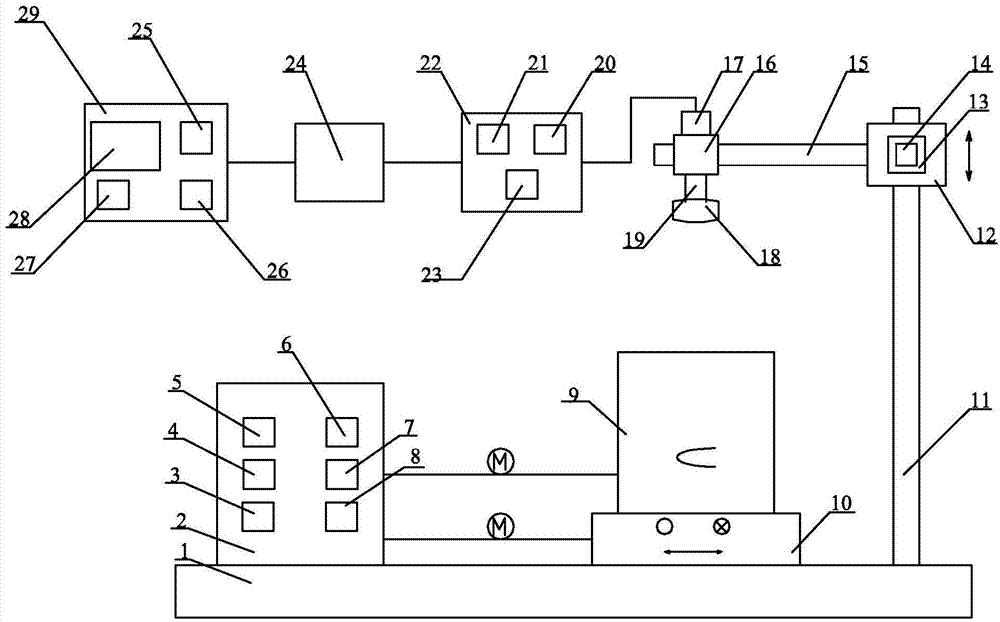
[0032] Specific implementation mode one: combine Figure 1-Figure 4 Describe this embodiment, this embodiment includes detection workbench 1, described surface defect detection device also includes motion control cabinet 2, grating surface unfolding unit, first image acquisition system unit and second image acquisition system unit, motion control cabinet 2 , the grating surface expansion unit and the first image acquisition system unit are arranged side by side on the detection workbench 1 from left to right, the second image acquisition system unit is connected with the first image acquisition system unit,

[0033] The motion control cabinet 2 includes a safety protection assembly 3, a parameter input device 4, a numerical display 5, a light source controller 6, a rotation controller 7 and a displacement controller 8, and the safety protection assembly 3, the parameter input device 4 and the numerical display 5 are composed of The light source controller 6, the rotation contr...

specific Embodiment approach 2

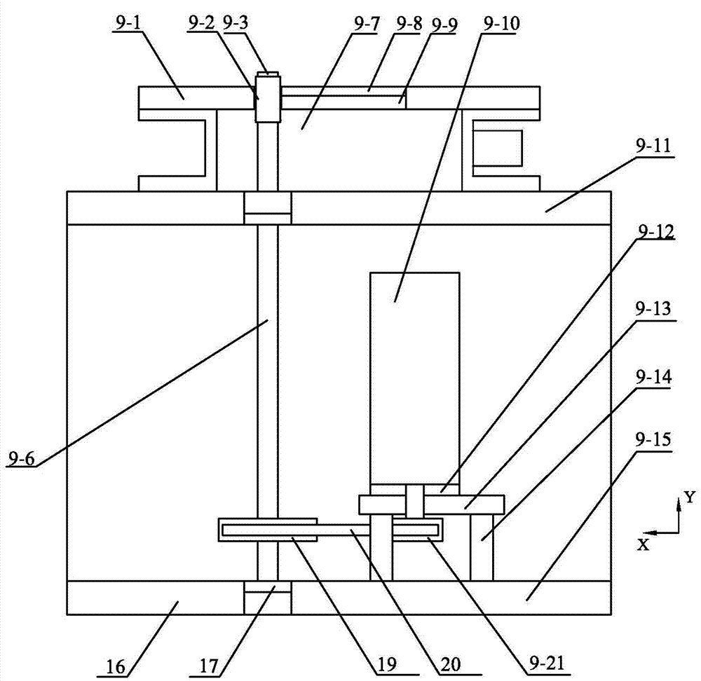
[0044] Specific implementation mode two: combination figure 1 and figure 2 The present embodiment is described. The grating unfolding mechanism 9 of the present embodiment includes a box body and a transmission light source, and the transmission light source is arranged on the box body. This is set up for ease of use. Other compositions and connections are the same as in the first embodiment.

specific Embodiment approach 3

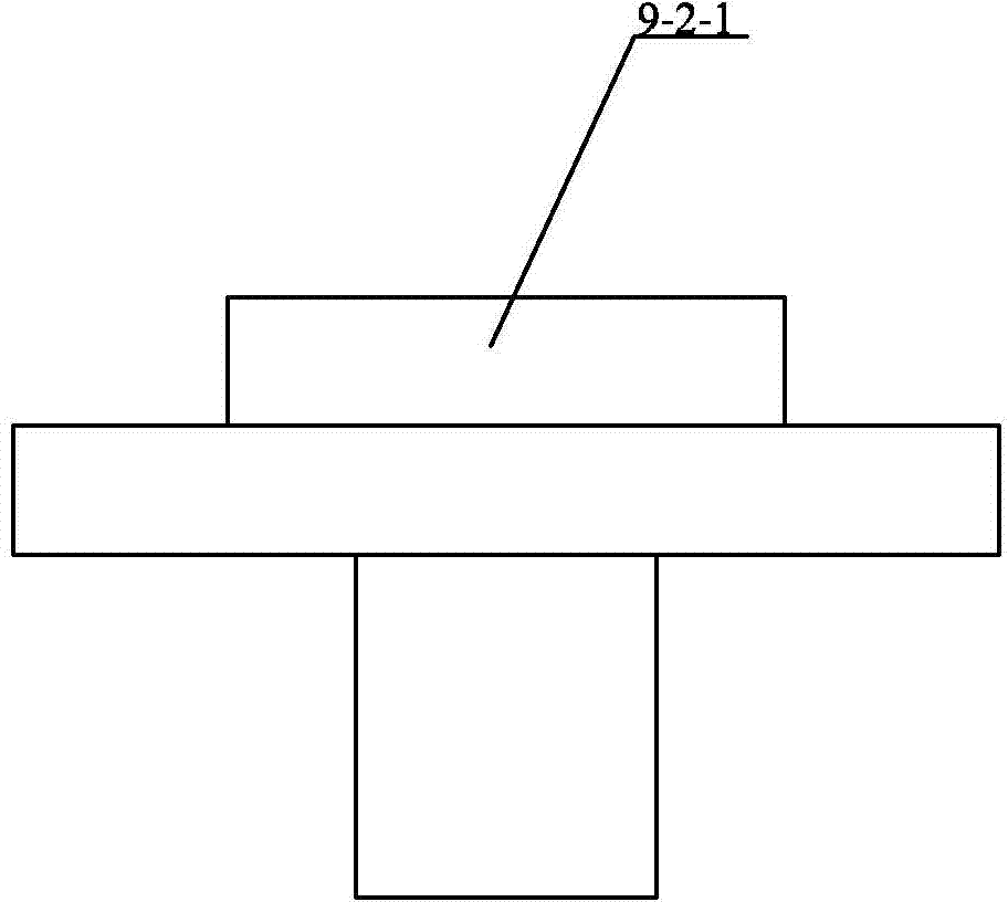
[0045]Specific implementation mode three: combination figure 2 Describe this embodiment, the box of this embodiment includes quick-change fixture group 9-2, upper miniature bearing 9-4, shaft 9-6, servo motor 9-10, box top plate 9-11, spacer 9-12 , Motor support plate 9-13, box shell 9-15, box bottom plate 9-16, lower miniature bearing 9-17, synchronous large pulley 9-19, tension synchronous belt 9-20, synchronous small pulley 9-21 and a plurality of motor support columns 9-14,

[0046] Casing top plate 9-11 and casing bottom plate 9-16 are respectively arranged on the upper and lower ends of casing shell 9-15, and shaft 9-6 is vertically arranged in casing casing 9-15, and the two ends of shaft 9-6 An upper miniature bearing 9-4 and a lower miniature bearing 9-17 are arranged at the upper end respectively, the quick-change clamp group 9-2 is arranged on the upper end of the shaft 9-6, and a plurality of motor support columns 9-14 are arranged on one side of the shaft 9-6. ...


PUM


Abstract

The invention provides an interactive semi-automatic grating surface defect detection device and a method using the device, and relates to a defect detection device and the method using the device. The problems that an existing grating surface defect detection device is low in detection precision, low in detection efficiency, poor in anti-interference performance and high in cost are solved. According to the detection device, a motion control cabinet, a grating surface unfolding unit and a first image collecting system unit are sequentially arranged on a detection worktable from left to right in parallel, and a second image collecting system unit and the first image collecting system unit are connected. The defect detection method has the advantages of being high in automation degree, high in detection precision and detection efficiency, high in objectivity and not prone to causing eyestrain. Alignment of the position of a grating to be detected is achieved by driving an electric two-dimensional translation table, and the alignment mode has the advantages of being high in objectivity, high in positioning precision and good in stability compared with manual alignment. The device and the method are used for interactive semi-automatic grating surface defect detection.

Description

technical field [0001] The invention relates to a grating surface defect detection device and a method for using the device, in particular to an interactive semi-automatic grating surface defect detection device and a method for using the device. Background technique [0002] Defect detection usually refers to the detection of surface defects of objects. Surface defect detection uses advanced machine vision detection technology to detect defects such as spots, pits, scratches, color differences, and defects on the surface of workpieces. Existing manufacturers generally use manual detection of grating surface defects, which has the following characteristics: the alignment of the position of the grating to be inspected needs to be done manually, which has the characteristics of strong robustness, poor positioning accuracy and high repeatability. Incandescent lamps are commonly used as transmitted light sources, which have the characteristics of low brightness and light source ...

Claims


Application Information

Patent Timeline
Patent Type & Authority Applications(China)
IPC IPC(8): G01N21/88
Inventor 王义文冯超李玉甫刘献礼屈冠彤廖益龙林长友梅恒刘勇刚
Owner HARBIN UNIV OF SCI & TECH
Why Eureka
Try Eureka