
Sensorless vector control system and method for permanent magnet synchronous motor

A technology of permanent magnet synchronous motor and vector control, which is applied in the direction of vector control system, control system, motor generator control, etc., and can solve problems affecting the reliability of vector control system, switching failure, and small induced electromotive force

Inactive Publication Date: 2014-01-22
SOUTHEAST UNIV
View PDF5 Cites 17 Cited by
  • Summary
  • Abstract
  • Description
  • Claims
  • Application Information

AI Technical Summary

Problems solved by technology

[0005] Sliding mode observers are commonly used to realize medium and high speed sensorless vector control of permanent magnet synchronous motors. The electromotive force realizes the rotor position and speed estimation. Since the induced electromotive force of the motor in the start-up and low-speed state is too small, the sliding mode observer cannot be applied in this area
[0006] In order to make up for the deficiencies of the sliding mode observer method in the low-speed region, in this region, the high-frequency injection method is often used instead of the sliding mode observer method to realize the sensorless vector control of permanent magnet synchronous motors at start-up and at low speeds {literature "Motor Modern Control Technology", edited by Wang Chengyuan, Xia Jiakuan, etc., Mechanical Industry Press, P279-295}, however, because the high-frequency injection normal vector control system introduces high-frequency signals, it is easy to interfere with the vector control system
[0007] In addition, the switching process of the motor from low speed to medium and high speed is very important. If a reliable switching method is not adopted, it will easily cause the switching failure of the two control methods and affect the reliability of the vector control system.

Method used


Image

  • Sensorless vector control system and method for permanent magnet synchronous motor
  • Sensorless vector control system and method for permanent magnet synchronous motor
  • Sensorless vector control system and method for permanent magnet synchronous motor

Examples


Embodiment Construction

[0053] In order to better understand the technical content of the present invention, specific embodiments are given together with the attached drawings for description as follows.

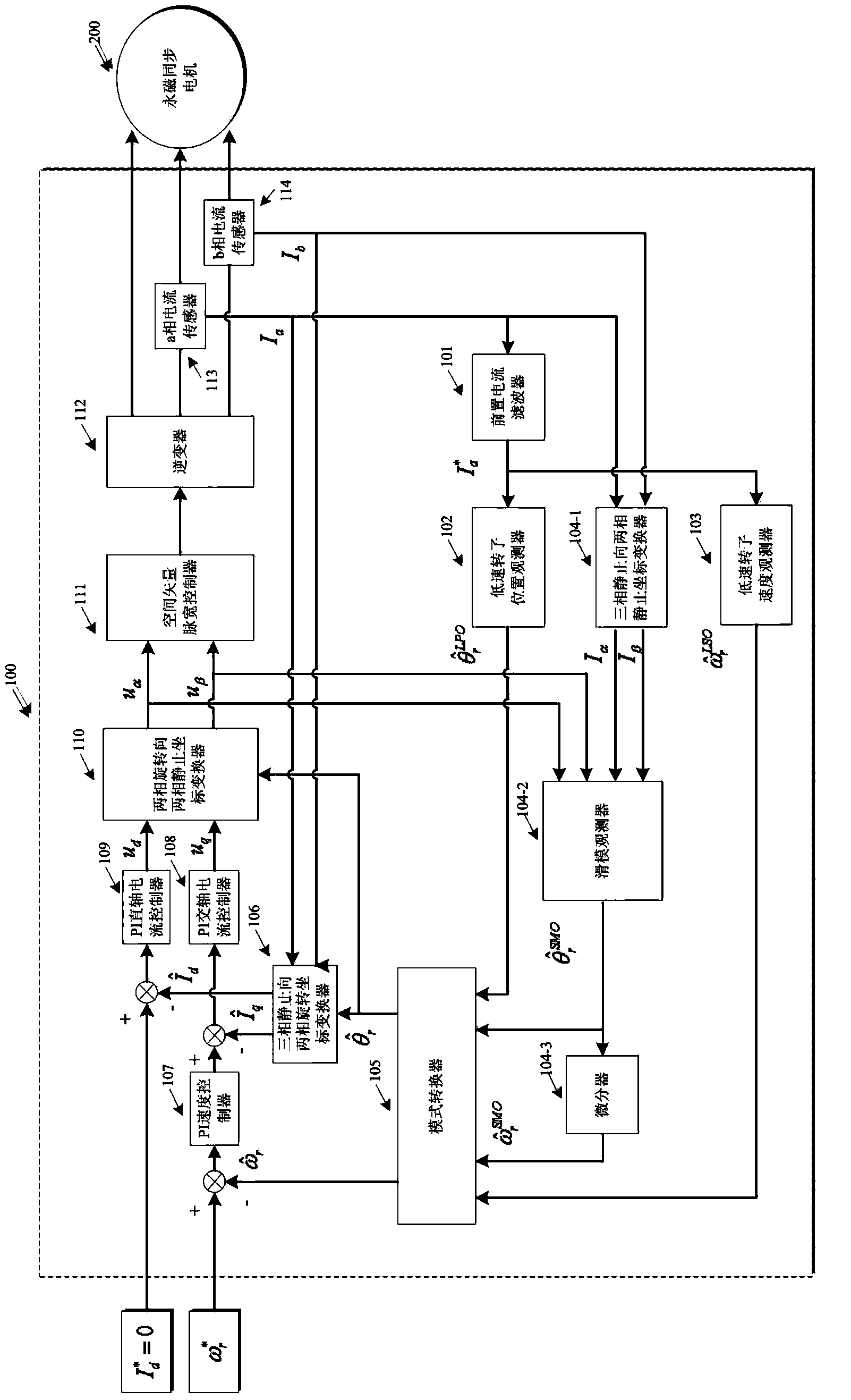
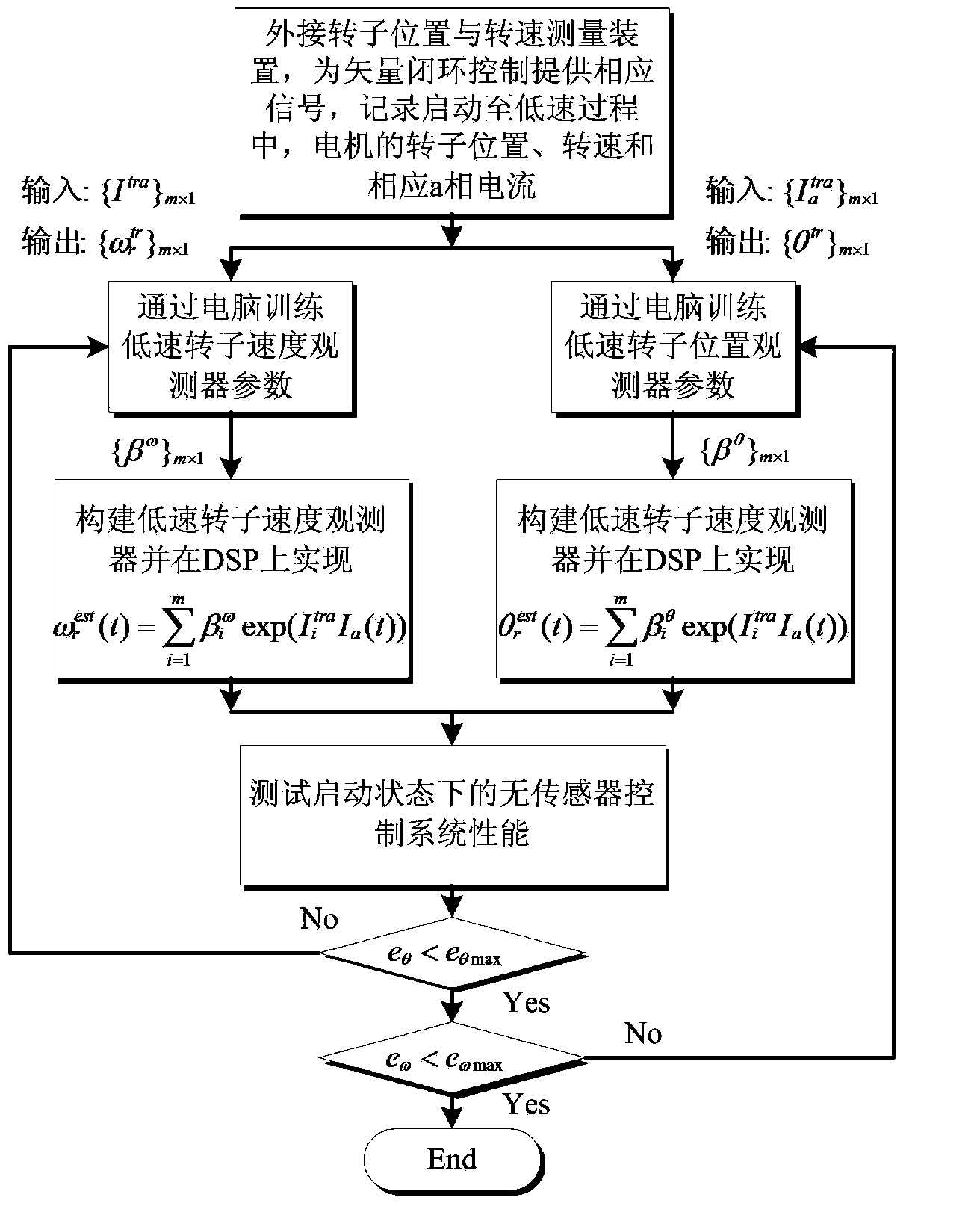
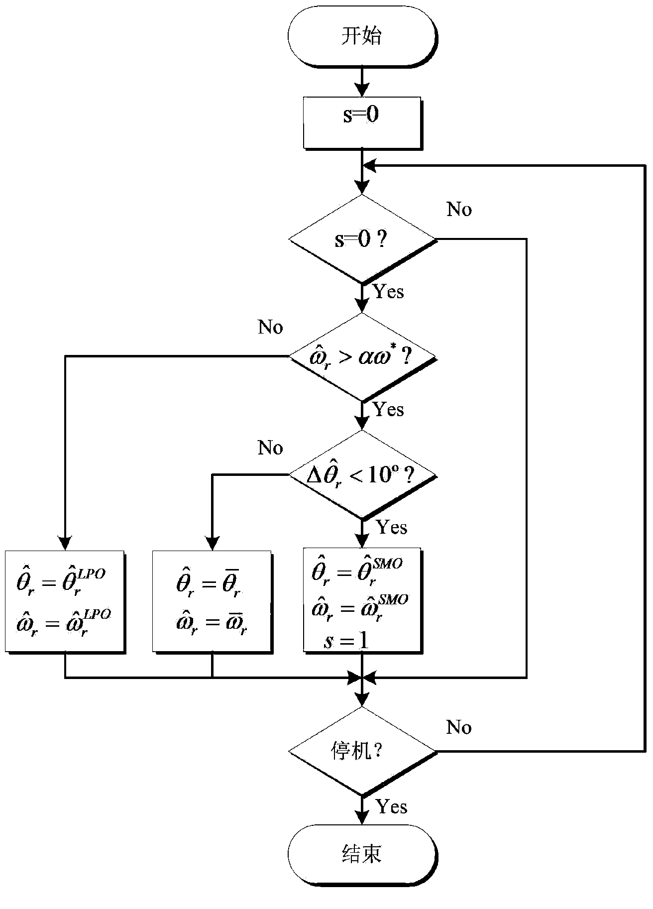
[0054] Such as figure 1 combine figure 2 , image 3 As shown, according to a preferred embodiment of the present invention, a sensorless vector control method of a permanent magnet synchronous motor, the method realizes the sensorless vector control of the permanent magnet synchronous motor in the range of starting, low speed, medium speed to full speed.

[0055] refer to figure 1 As mentioned above, the sensorless vector control system of permanent magnet synchronous motor includes: pre-current filter (101), low-speed rotor position observer (102), low-speed rotor speed observer (103), three-phase stationary to two-phase stationary coordinates Converter (104-1), sliding mode observer (104-2), differentiator (104-3), mode converter (105), three-phase stationary to two-phase rotating coordinate ...


PUM


Abstract

The invention provides a sensorless vector control system and method for a permanent magnet synchronous motor. The method comprises the steps of starting low-speed control, medium-high speed control and transition area control, wherein the starting of low-speed control respectively builds a low-speed rotor position observer and a low-speed rotor speed observer on the basis of a regression model; the medium-high speed control is realized through a traditional sliding-mode observer; the transition area control guarantees the smoothness of switching process by simultaneously considering two factors of rotating speed and rotor position error. By adopting the scheme provided by the invention, the reliable operation of the sensorless permanent magnet synchronous motor within the scope of full speed can be guaranteed, the sensorless permanent magnet synchronous motor is independent of a motor mathematical model in the low-speed modeling process, and the high-frequency signals are not required to be superposed; estimated results are not influenced by the parameters precision; the medium-high speed control is still realized through the sliding-mode observer; the characteristics of strong robustness and stable performance of the sliding-mode observer are retained. The switching process of two methods guarantees the smooth transition of the switching process by simultaneously considering the two factors of the rotating speed and the rotor position error.

Description

technical field [0001] The invention relates to the control field of permanent magnet synchronous motors, in particular to a sensorless vector control system and control method of permanent magnet synchronous motors, which can realize the permanent magnet synchronous , Sensorless vector control in the range of low speed, medium speed to full speed. Background technique [0002] The permanent magnet synchronous motor is developed from the wound synchronous motor, which has the advantages of high efficiency, simple structure, easy control, and excellent performance. Its control process is relatively simple compared with asynchronous motors. As the performance of permanent magnet materials continues to improve and the price continues to decline, the application of control systems for permanent magnet synchronous motors occupies an increasingly important position. [0003] In the vector control speed regulation system of ordinary permanent magnet synchronous motors, in order to...

Claims


Application Information

Patent Timeline
IPC IPC(8): H02P21/13H02P25/02
Inventor 林鹤云陆婋泉
Owner SOUTHEAST UNIV
Learn More