
Low-power-consumption high-gain broadband frequency mixer

A mixer, high gain technology, applied in the field of low power consumption high gain wideband mixer, can solve the problems of mixer gain and bandwidth cannot be improved at the same time, the traditional structure cannot improve the gain, the bandwidth is narrow, etc. Gain, Power Reduction, Gain and Bandwidth Increase Effect

Active Publication Date: 2014-01-22
NANJING QINHENG MICROELECTRONICS CO LTD
View PDF6 Cites 20 Cited by
  • Summary
  • Abstract
  • Description
  • Claims
  • Application Information

AI Technical Summary

Problems solved by technology

When using a tuned load, the limited Q value of the inductance unit and the limited output resistance of the switch stage restrict the reduction of the load conductance, which is an important reason why the traditional structure cannot increase the gain; ②The bandwidth of the traditional Gilbert mixer is narrow The main reason is that the susceptance component of the tuned load increases too fast at the frequency away from the resonance point, so that the voltage generated by the current on the load drops rapidly as the frequency deviates from the resonance point; ③ By increasing the Q value of the load inductance, the frequency mixing The gain and bandwidth of the device cannot be improved at the same time, and the gain and bandwidth are often contradictory, so a trade-off is required

Method used


Image

  • Low-power-consumption high-gain broadband frequency mixer
  • Low-power-consumption high-gain broadband frequency mixer
  • Low-power-consumption high-gain broadband frequency mixer

Examples


Embodiment Construction

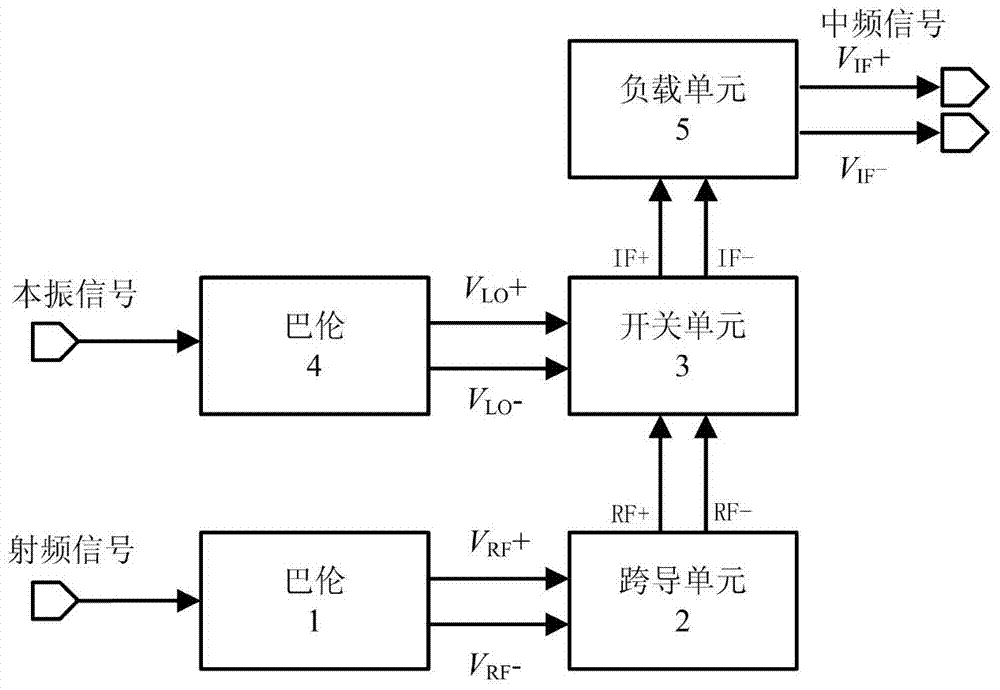
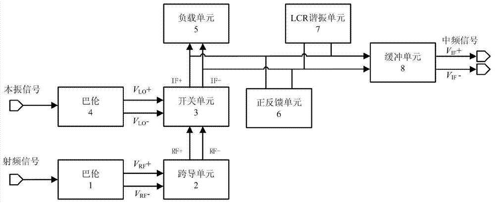
[0026] see image 3 , the radio frequency signal is converted into a differential voltage signal V by the radio frequency balun unit 1 RF + and V RF -Send into the transconductance unit 2, the transconductance unit 2 converts the input voltage signal into a current signal and sends it to the switch unit 3, while the local oscillator signal is converted into a differential voltage signal V by the balun unit 4 LO + and V LO - Afterwards, it is also added to the switch unit 3 to make it switch the radio frequency current at the local oscillator frequency. The switch unit 3 outputs the intermediate frequency differential current signals IF+ and IF- to be connected to the load unit 5 . The above part and the circuit block of the traditional Gilbert structure mixer figure 1exactly the same. The present invention adds a positive feedback unit 6, an LCR resonant unit 7 and a buffer unit 8 after the switch unit 3, and together with the load unit 5 they form a new load unit as the ...


PUM


Abstract

The invention discloses a low-power-consumption high-gain broadband frequency mixer which adopts a basic structure of a Gilbert frequency mixer and is provided with a radio-frequency balun, a local oscillator balun, a transconductance unit, a switch unit and a load unit provided with a differential inductor and connected with a load-end parasitic capacitor in parallel, wherein the radio-frequency balun is used for converting an input radio-frequency single-ended signal into a differential signal and outputting the differential signal to the transconductance unit; the transconductance unit is used for converting a radio-frequency voltage signal into a radio-frequency current and inputting the radio-frequency current to the switch unit; the local oscillator balun is used for converting an input local oscillator single-ended signal into a differential signal and outputting the differential signal to the switch unit; the switch unit is used for multiplying the input radio-frequency differential signal by the input local oscillator differential signal and outputting a medium-frequency differential signal through the load unit provided with the differential inductor and connected with the load-end parasitic capacitor in parallel. The low-power-consumption high-gain broadband frequency mixer is characterized in that a positive feedback unit, an LCR resonance unit and a buffer unit are additionally arranged behind the switch unit and form a new load unit with the load unit provided with the differential inductor and connected with the parasitic capacitor in parallel; a final medium-frequency differential signal is output by the buffer unit.

Description

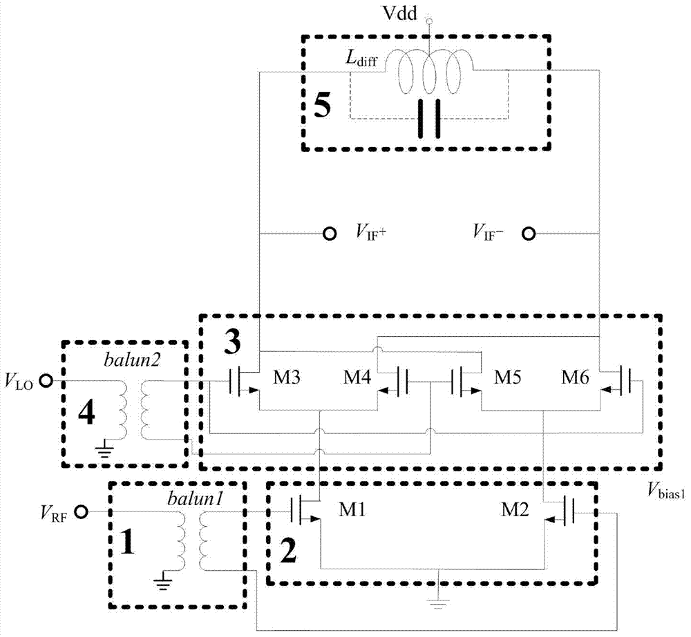
technical field [0001] The invention relates to a mixer in a millimeter-wave circuit, especially a low-power high-gain broadband mixer, which adopts MOS technology and has great advantages in a millimeter-wave circuit. The design structure is simple, and the mixer can be simultaneously Obtain high gain and broadband characteristics, and can greatly reduce the power consumption of the mixer while having the same gain and bandwidth performance as the traditional mixer. Background technique [0002] In 1968, BarrieGilbert proposed the Gilbert double-balanced multiplier structure for the first time, and it was widely used in mixers (hereinafter referred to as "Gilbert mixer"). The circuit block diagram and circuit principle are as follows figure 1 , figure 2 As shown, the radio frequency signal RF converts the single-ended signal into differential signals RF+ and RF- through the balun, and connects the gates of the common source structure MOS transistors M1 and M2 of the trans...

Claims


Application Information

Patent Timeline
IPC IPC(8): H03D7/12
Inventor 李智群王冲李芹曹佳王志功
Owner NANJING QINHENG MICROELECTRONICS CO LTD
Learn More