Simple light guide switching circuit

A kind of photoconductive switch, circuit technology

Inactive Publication Date: 2014-01-22
CHENGDU HONGSHAN TECH
View PDF5 Cites 3 Cited by
  • Summary
  • Abstract
  • Description
  • Claims
  • Application Information

AI Technical Summary

Problems solved by technology

However, most of them are composed of more electronic components, and the circuit is more complicated, which is not suitable for the integration of small circuit boards.

Method used


Image

  • Simple light guide switching circuit

Examples


Embodiment

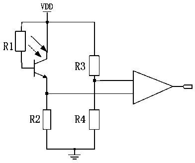
[0015] Such as figure 1 The simple photoconductive switch circuit shown includes a phototransistor, an amplifier, a resistor R1, a resistor R2, a resistor R3 and a resistor R4, and the two ends of the resistor R1 are respectively connected to the base and the collector of the phototransistor. The collector of the phototransistor is connected to the power supply and the emitter is connected to the ground through the resistor R2. After the resistor R3 is connected in series with the resistor R4, one common end is grounded, and the other common end is connected to the collector of the phototransistor. One input end of the amplifier is connected to the emitter of the phototransistor, and the other input end is connected between the resistor R3 and the resistor R4.

[0016] The resistance ratio of the resistor R3 and the resistor R4 is 1:3.

[0017] The output end of the amplifier is connected to the A / D converter.

[0018] The resistance values ​​of the resistor R2 and the resis...


PUM


Abstract

The invention discloses a simple light guide switching circuit which comprises a phototransistor, an amplifier, a resistor R1, a resistor R2, a resistor R3 and a resistor R4, wherein the two ends of the resistor R1 are connected with a base and a collector of the phototransistor respectively; the collector of the phototransistor is connected with a power supply, and an emitter of the phototransistor is grounded through the resistor R2; after the resistor R3 is connected in series with the resistor R4, a common end is grounded; the other common end is connected with the collector of the phototransistor; an input end of the amplifier is connected with the emitter of the phototransistor; and another input end of the amplifier is connected between the resistor R3 and the resistor R4. The circuit has the advantages that the circuit is high in control sensitivity and simple, and facilitates miniature integration.

Description

technical field [0001] The invention relates to a circuit structure, in particular to a simple photoconductive switch circuit. Background technique [0002] Photoconductive switch is a kind of semiconductor optoelectronic device that has developed rapidly in the past ten years. Its working principle is to use the photoelectric effect of the semiconductor material to modulate the resistivity of the material, that is, when the light is irradiated on the semiconductor material, the electrons in the valence band in the material absorb photon energy, jump into the conduction band through the forbidden band, and make the electron concentration in the conduction band and The number of holes in the valence band increases, that is, the photogenerated electron-hole pairs are excited, and the semiconductor material produces a photoelectric effect. Nowadays, more and more photoconductive switches are used, and more and more switching circuits are developed using the characteristics of ...

Claims


Application Information

Patent Timeline
Patent Type & Authority Applications(China)
IPC IPC(8): H03K17/78
Inventor 黄友华
Owner CHENGDU HONGSHAN TECH
Why Eureka
Try Eureka