Optical frequency supervising device

A monitoring device and optical frequency technology, which is applied in the field of optical communication, can solve the problems of increasing the difficulty and cost of optical frequency monitoring devices, increasing the complexity of the packaging process, etc., and achieve the effect of reducing difficulty, cost and complexity

Active Publication Date: 2014-01-22
HUAWEI TECH CO LTD
View PDF9 Cites 1 Cited by
  • Summary
  • Abstract
  • Description
  • Claims
  • Application Information

AI Technical Summary

Problems solved by technology

However, FP Ethernet needs to collimate the optical signal. Therefore, a lens group is required to complete it, and an additional packaging process is required, which increases the complexity of the packaging process and also increases the difficulty and cost of making an optical frequency monitoring device.

Method used


Image

  • Optical frequency supervising device
  • Optical frequency supervising device
  • Optical frequency supervising device

Examples


Embodiment 1

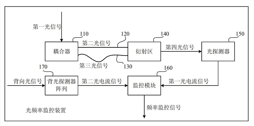
[0033] Below with figure 1 As an example, the optical frequency monitoring device provided by the embodiment of the present invention is described in detail, figure 1 This is a schematic structural diagram of an optical frequency monitoring device provided in an embodiment of the present invention. like figure 1 As shown, the optical frequency monitoring device includes: a coupler 110 , a first waveguide 120 , a second waveguide 130 , a diffractive region 140 , a light detector 150 with a clear aperture, a backlight detector array 160 and a monitoring module 170 .

[0034] exist image 3 , the coupler 110 is configured to receive a first optical signal, divide the first optical signal into a second optical signal and a third optical signal in equal proportions, and combine the second optical signal and the third optical signal Optical signals are transmitted through the first waveguide and the second waveguide, respectively, to the diffractive region.

[0035] Specifically...


PUM


Abstract

The invention relates to an optical frequency supervising device, which comprises a coupler, which is used for receiving optical signals and combining and dividing into a first optical signal, and equally dividing the first optical signal into a second optical signal and a third optical signal, and transmitting the second optical signal and the third optical signal to a diffraction zone by a first waveguide and a second waveguide respectively; a diffraction zone, which is used for diffracting the second optical signal and the third optical signal, thereby producing many fourth optical signals with space interference fringes; an optical detector, which is used for acquiring a first frequency valve of the fourth optical signal, and generating the first photo-signal according to the first frequency; a backlight detector array, which is used for acquiring a second optical frequency valve of the received backlight optical signal, and generating a second photo-signal according to the second optical frequency valve; a monitoring module, which is used for generating a frequency monitoring signal according to the first photo-signal and the second photo-signal.

Description

technical field [0001] The invention relates to the field of optical communication, in particular to an optical frequency monitoring device. Background technique [0002] The 40G Time-Wavelength Division Multiplexing (TWDM for short) passive optical network (Passive Optical Network, PON for short) has been preliminarily determined by the standards organization as the standard framework of the next-generation passive optical network. In the 40G TWDM PON, there is a 4X10Gbps optical line terminal (Optical Line Terminal, OLT for short) optical transmitting module. The module requires 4 optical transmitters with independent frequencies to work independently, with a frequency interval of 100 GHz. [0003] According to the regulations of the International Telecommunication Union, when an optical transmitter module with a frequency interval of 100GHz transmits an optical signal, the stability of the transmitted optical frequency must be controlled within ±10GHz. Usually, the OLT ...

Claims


Application Information

Patent Timeline
Patent Type & Authority Applications(China)
IPC IPC(8): H04B10/07
CPCG02B6/4215G02B6/29385H04B10/07957H04J14/02
Inventor 王磊周小平
Owner HUAWEI TECH CO LTD
Why Eureka
Try Eureka