
Reinforced concrete frame joint area plus steel plate and steel wire mesh wrapped reinforcement structure and preparation method

A technology of reinforced concrete and reinforced concrete columns, which is applied to structural elements, building reinforcements, building components, etc., can solve problems such as structural collapse, failure to achieve the design goals of strong columns and weak beams, and failure to consider the multi-dimensionality of ground motion input. Prevent early fall off, bear reasonable force, and strengthen the effect of good effect

Inactive Publication Date: 2015-10-28
BEIJING UNIV OF TECH
View PDF7 Cites 0 Cited by
  • Summary
  • Abstract
  • Description
  • Claims
  • Application Information

AI Technical Summary

Problems solved by technology

The current design codes only carry out separate seismic design along the two main axis directions and the verification of "strong columns and weak beams" of joints, without considering the multi-dimensional nature of the ground motion input, which may lead to X (or Y) The structure designed according to "strong column and weak beam" in one direction cannot achieve the design goal of "strong column and weak beam" under multi-dimensional earthquake action, resulting in the failure of reinforced concrete beam-column joints and column joints before the failure of beam joints. eventually lead to the overall collapse of the structure

Method used


Image

  • Reinforced concrete frame joint area plus steel plate and steel wire mesh wrapped reinforcement structure and preparation method
  • Reinforced concrete frame joint area plus steel plate and steel wire mesh wrapped reinforcement structure and preparation method
  • Reinforced concrete frame joint area plus steel plate and steel wire mesh wrapped reinforcement structure and preparation method

Examples


Embodiment Construction

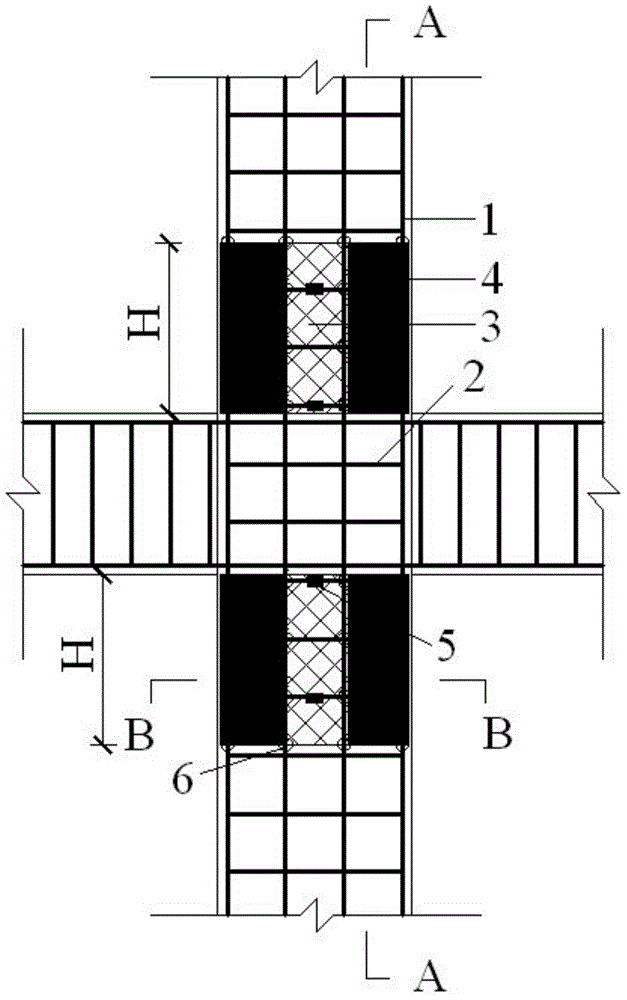
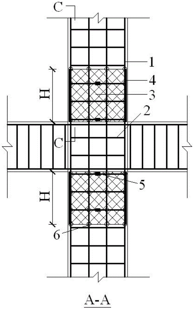
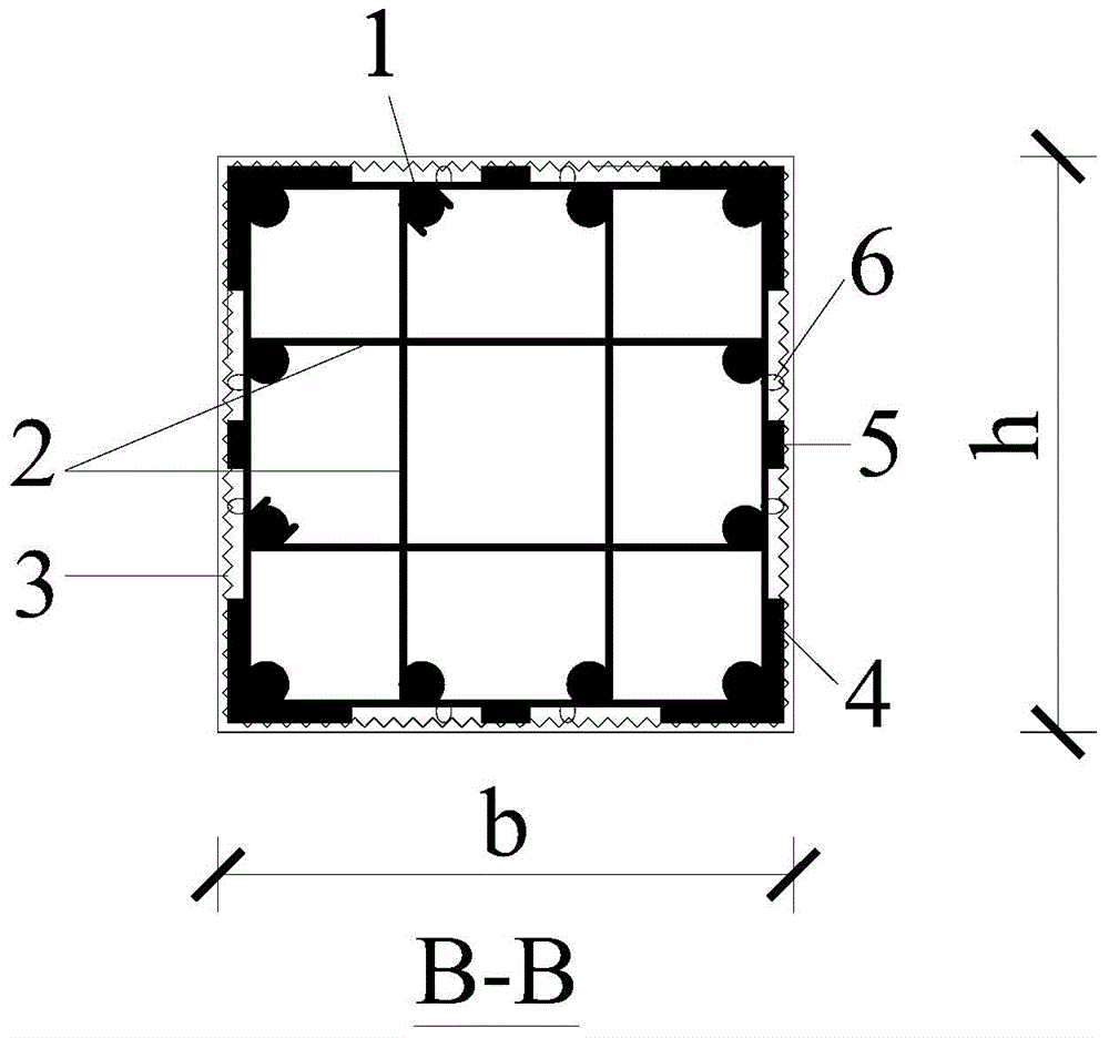
[0029] A reinforcement structure wrapped with steel plates and steel wire mesh in the node area of ​​a reinforced concrete frame, including a reinforcement cage, which is formed by binding and fixing the longitudinal bars 1 and stirrups 2 of a reinforced concrete column; The net 3, the L-shaped steel plate 4, the spacer block 5 and the binding wire 6; the reinforced structure refers to: in the beam-column node area, the upper and lower corners of the column node are partially covered with L-shaped steel plates 4, L The height of the shaped steel plate along the direction of the column height is H, H takes the larger value of 1.5h and 500mm, h is the cross-sectional height of the reinforced concrete column; for the upper part of the column joint, the lower edge of the L-shaped steel plate and the middle beam section of the frame joint The upper edge coincides; for the lower part of the column joint, the upper edge of the L-shaped steel plate coincides with the lower edge of the ...


PUM


Abstract

The invention relates to a reinforced concrete frame node region reinforcing structure externally provided with steel plates and wrapped by a steel wire mesh and a manufacturing method thereof and belongs to the field of reinforced concrete beam column node area anti-seismic performance reinforcing. L-shaped steel plates are arranged on the outside of four corners of the column sections of the upper portion and lower portion of a column node on the basis of an original beam column node, the steel plates are fixed with a column node steel bar cage by adopting resistance spot welding, and the steel wire mesh is wrapped on the outside of the steel plates and fixed on the column node steel bar cage through binding wires to form a node reinforcing structure with the L-shaped steel plates. The steel plates and the steel wire mesh provide a good restraining effect on concrete and prevent concrete at the corners from cracking and falling too early under the inclined earthquake effect. Meanwhile, the steel plates and the steel wire mesh can share a part of bending moment and shearing force of a node region and improve anti-seismic performance such as normal section and inclined section bearing capacity and ductility of the node to some extent.

Description

technical field [0001] The invention relates to a reinforcement structure wrapped with steel plates and steel wire mesh in the joint area of ​​a reinforced concrete frame and a preparation method thereof, belonging to the field of strengthening the seismic performance of reinforced concrete columns. Background technique [0002] Earthquake motion is multi-dimensional, and its effect on structures and their components is spatial. Therefore, elastoplastic analysis that simplifies the structure into a plane model and only considers unidirectional earthquake motion cannot fully reflect and reveal the nature of structural seismic response. Item 1 of Article 5.1.1 of my country's "Code for Seismic Design of Buildings" (GB50011-2010) stipulates that in general, at least the horizontal seismic action is calculated in the two main axis directions of the building structure, and the horizontal seismic action in each direction is determined by the The lateral force member bears. The cur...

Claims


Application Information

Patent Timeline
Patent Type & Authority Patents(China)
IPC IPC(8): E04B1/58E04B1/98E04C5/01E04C5/04E04G21/00E04G21/12
Inventor 李振宝宋坤
Owner BEIJING UNIV OF TECH
Learn More