
Independent ventilation cage flow measurement method, cage box external pressure difference measurement method, control system and control method

A control system and pressure difference technology, applied in the field of breeding systems, can solve the problems of large manpower and time consumption, illness of experimental animals, high risk, etc., and achieve the effect of avoiding inconvenience, wide measurement range and wide application range

Inactive Publication Date: 2014-02-05
上海鸣励实验室科技发展有限公司
View PDF10 Cites 12 Cited by
  • Summary
  • Abstract
  • Description
  • Claims
  • Application Information

AI Technical Summary

Problems solved by technology

Since the fan in the system adopts an open-loop control mode, the breeding site needs staff to monitor it in real time. When the air inlet condition changes due to filter blockage, the staff needs to change the working status of the fan according to the actual situation, so as to control the cage. To adjust the air exchange volume of the cages, the environment in each cage in the IVC system maintains the pressure and air exchange volume value set by the experiment requirements, otherwise the experimental animals in the cages will be sick or die, so the operation of the system will consume a lot of energy. Manpower and time, and there are greater risks

Method used


Image

  • Independent ventilation cage flow measurement method, cage box external pressure difference measurement method, control system and control method
  • Independent ventilation cage flow measurement method, cage box external pressure difference measurement method, control system and control method
  • Independent ventilation cage flow measurement method, cage box external pressure difference measurement method, control system and control method

Examples


Embodiment Construction

[0051] The present invention will be further described in detail below in conjunction with the accompanying drawings and specific embodiments.

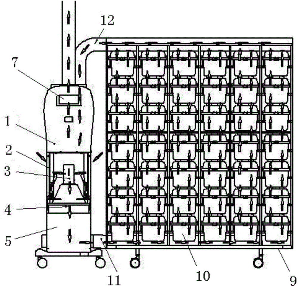
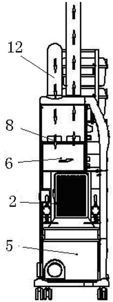
[0052] The control system of the independent ventilation cage provided by the present invention, wherein the independent ventilation cage includes a conventional cage 9 , a cage 10 , an air supply duct 11 , and an exhaust duct 12 . The control system, such as figure 2 , image 3 As shown, it includes a chassis 1, an air intake fan 3, an air intake box 5, an exhaust fan 8, an exhaust box 6, a primary filter 2, a secondary filter 4, a display unit 7 and a control unit.

[0053] The chassis 1 is made of plastic material, and the air intake 3, the air intake box 5, the exhaust fan, the exhaust box 6, the primary filter 2, the secondary filter 4 and the control unit are all located in the chassis 1.

[0054] The case 1 is provided with an air inlet, and the inner side of the air inlet is provided with a primary filter 2 , and in this em...


PUM


Abstract

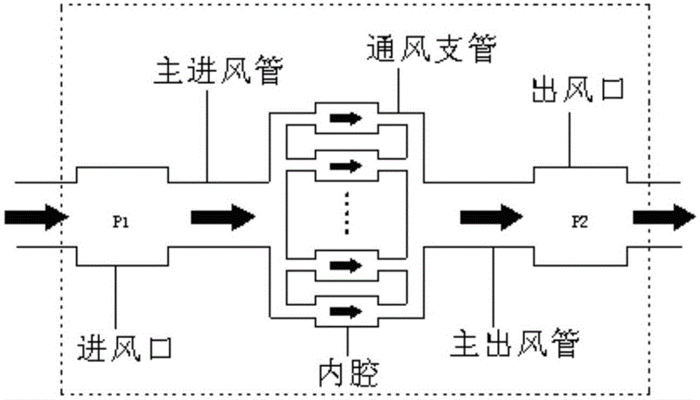
The invention discloses an independent ventilation cage flow measurement method which comprises the following steps of (1) dividing the voltage of an air inlet fan motor into N sampling points and dividing the voltage of an air outlet fan motor into M sampling points; (2) controlling the air inlet fan motor to work on a first sampling point, controlling the air outlet fan motor to work on a 0 sampling point and an M sampling point, collecting pressure difference between an air inlet box and an air outlet box through a pressure difference sensor, and utilizing a standard flow measurement instrument to demarcate flow in an independent ventilation cage of the air outlet fan motor on each of the sampling points; (3) repeating the step (1) and the step (2) when the air inlet fan motor works on other sampling points; (4) performing regression analysis on M+1 groups of pressure difference-flow data to obtain N pressure difference-flow curves meeting the following formula: deltaP+ K1 (v+ K2) 2= C, demarcating N groups of weight factors K1 and K2 when the air inlet fan motor works on different sampling points, and storing the N groups of weight factors K1 and K2 into a controller; (5) during actual operation, selecting the nearest voltage sampling point of an air inlet fan according to the voltage of the air inlet fan motor through the controller, and calculating the flow v by means of the weight factors of the nearest voltage sampling point and the measured pressure difference. The invention further discloses a cage box external pressure difference measurement method and a control method based on the independent ventilation cage flow measurement method and the cage box external pressure difference measurement method.

Description

technical field [0001] The invention relates to a breeding system for experimental rodents, in particular to a control system and control method in an independent ventilation cage, and a flow measurement method involved in the control system and method, which can control experimental rodents Indicators such as air exchange rate, external pressure difference and air cleanliness of the living space. Background technique [0002] At present, in the research and development and production process of biology and pharmaceuticals, animal experiments are generally required. Since the animals for experiments must be kept in a sterile environment, an independent ventilation cage (IVC) system has emerged. This system is mainly composed of cages, cages, air supply and exhaust devices (main unit), air supply ducts and exhaust ducts. The cages are arranged on the cages in sequence, and the air inlet and air supply on each cage The pipes are connected, and the air outlet on each cage is c...

Claims


Application Information

Patent Timeline
Patent Type & Authority Applications(China)
IPC IPC(8): A01K1/00A01K1/03G01F1/34G01L13/00
Inventor 钱力钱鸣王继国
Owner 上海鸣励实验室科技发展有限公司
Learn More