Upright normal pressure amorphous iron core heat treatment furnace

An amorphous iron core and heat treatment furnace technology, applied in heat treatment furnaces, heat treatment equipment, furnaces, etc., can solve the problems of poor product consistency and unsatisfactory uniformity of tank heating temperature, etc., to reduce heat treatment requirements and product magnetic properties. Excellent academic performance and improved product consistency

Inactive Publication Date: 2014-02-05
江阴市晶磁电子有限公司
View PDF7 Cites 9 Cited by
  • Summary
  • Abstract
  • Description
  • Claims
  • Application Information

AI Technical Summary

Problems solved by technology

[0002] Amorphous iron cores are now widely used in aviation transformers, railway control system transformers, mechanical parts quenching equipment transformers, laser power transformers, power transformers, power transformers, etc. The coiled iron core is directly and continuously wound the strip into a ring shape. After the winding is formed, it needs to undergo heat treatment to eliminate the stress inside the material and improve the magnetic properties of the iron core. The current amorphous iron core heat treatment furnace is used for Tank body, stacking bracket, heating rod and insulation layer; the tank body is cylindrical, the insulation layer is arranged outside the tank body, the heating rod is arranged between the tank body and the insulation layer, and the stacking bracket is arranged in the tank body; Crystalline core heat treatment furnace heats the amorphous core in a vacuum state, so the tank body must be cylindrical and has relatively high production requirements. At the same time, the uniformity of the heating temperature in the tank body is not ideal, and the product consistency is poor.

Method used


Image

  • Upright normal pressure amorphous iron core heat treatment furnace

Examples


Embodiment Construction

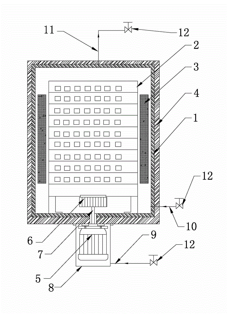
[0009] Such as figure 1 As shown, the vertical cabinet type atmospheric pressure amorphous iron core heat treatment furnace includes a tank body 1, a stacking bracket 2, a heating rod 3 and an insulation layer 4; the insulation layer 4 is arranged on the outside of the tank body 1, and the stacking bracket 2 is arranged on the tank body Inside the body 1; it is characterized in that it also includes a motor 5, a fan 6, a rotating shaft 7, a sealing cover 8, a first air delivery pipe 9, a second air delivery pipe 10 and an exhaust pipe 11; the tank body 1 is a square long tank; a heating rod 3 is set inside the tank body 1; the motor 5 is set outside the insulation layer 4 at the bottom of the tank body 1, the fan 6 is set inside the tank body 1, one end of the rotating shaft 7 is connected to the motor 5, and the other end of the rotating shaft 7 passes through the insulation layer 4 and the tank The body 1 is connected with the fan 6, the sealing cover 8 is arranged on the in...


PUM


Abstract

The invention relates to an upright normal pressure amorphous iron core heat treatment furnace. The heat treatment furnace comprises a tank body, a pile support, heating rods and an insulating layer, wherein the insulating layer is arranged outside the tank body; the pile support is arranged in the tank body. The heat treatment furnace is characterized by also comprising a motor, a fan, a rotating shaft, a seal cover, a first gas pipe, a second gas pipe and an exhaust pipe; the heating rods are arranged inside the tank body or between the insulating layer and the tank body; the motor is arranged outside the insulating layer; the fan is arranged in the tank body; one end of the rotating shaft is connected with the motor and the other end of the rotating shaft is connected with the fan after passing through the insulating layer and the tank body; the seal cover is arranged on the insulating layer and covers the motor; the first and second gas pipes are used for inputting gases into the tank body; the exhaust pipe is used for exhausting gases out of the tank body. The heat treatment furnace has the advantages that the heat treatment furnace can achieve heat treatment of amorphous iron cores in a normal pressure state and has good uniformity of heating temperatures.

Description

technical field [0001] The invention relates to a heat treatment furnace, in particular to a vertical cabinet type atmospheric pressure amorphous iron core heat treatment furnace. Background technique [0002] Amorphous iron cores are now widely used in aviation transformers, railway control system transformers, mechanical parts quenching equipment transformers, laser power transformers, power transformers, power transformers, etc. The coiled iron core is directly and continuously wound the strip into a ring shape. After the winding is formed, it needs to undergo heat treatment to eliminate the stress inside the material and improve the magnetic properties of the iron core. The current amorphous iron core heat treatment furnace is used for Tank body, stacking bracket, heating rod and insulation layer; the tank body is cylindrical, the insulation layer is arranged outside the tank body, the heating rod is arranged between the tank body and the insulation layer, and the stacki...

Claims


Application Information

Patent Timeline
Patent Type & Authority Applications(China)
IPC IPC(8): C21D1/74C21D9/00
Inventor 崔宇岑
Owner 江阴市晶磁电子有限公司
Why Eureka
Try Eureka