Novel heating mantle
A heating cover, a new type of technology, applied in textiles and papermaking, lamination devices, lamination, etc., can solve the problems of unevenness, slow heating of the heating cover, etc., achieve the effect of fast temperature rise and drop, increase vehicle speed, and realize temperature edge compensation
- Summary
- Abstract
- Description
- Claims
- Application Information
AI Technical Summary
Problems solved by technology
Method used
Image

Examples
Embodiment Construction
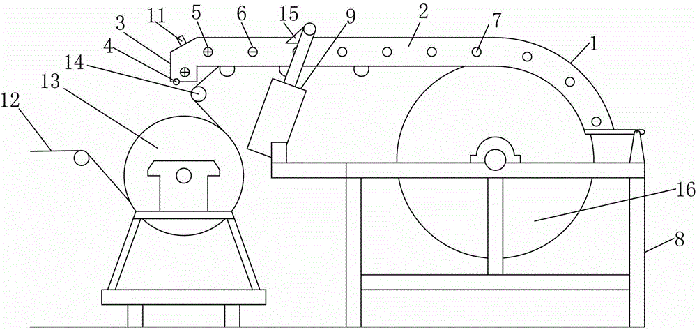
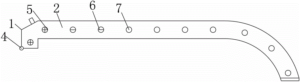
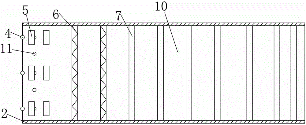
[0010] The specific implementation manners of the present invention will be described in further detail below in conjunction with the accompanying drawings.
[0011] Depend on Figure 1 to Figure 3 Given, the present invention includes a frame and a heating cover body whose right end is rotatably fixed on the frame. The front and rear sides of the heating cover body 1 are provided with heat preservation side plates 2, and the left part of the side section of the heating cover body 1 is linear, and the right part is linear. Semi-circular, the left end of the heating cover body 1 has a "7"-shaped bend 3 downward, and a plurality of thermocouples 4 are arranged longitudinally at the port of the bend 3, and the heating cover body 1 on the right side of the thermocouple 4 is horizontally spaced There are multiple groups of gold heating short tubes 5 arranged at vertical intervals and corresponding to the thermocouples 4. The heating cover body 1 on the right side of the gold heatin...
PUM
 Abstract
Description
Claims
Application Information
PatSnap Eureka turns technology decisions into work you can execute. Powered by our Innovation Knowledge Graph, it runs expert workflows across engineering, life sciences, materials and intellectual property. Get your review-ready output in minutes.


