
Non-electric coupling multi-section differential detonating circuit

A micro-differential detonation and network technology, applied in the direction of blasting tubes, weapon accessories, offensive equipment, etc., can solve the problems of expensive detonating cord, blasting operation accidents, high blasting costs, etc., to achieve low prices, reduce blasting costs, and spread explosions reliable effect

Inactive Publication Date: 2014-02-05
WUHAN UNIV OF SCI & TECH
View PDF4 Cites 4 Cited by
  • Summary
  • Abstract
  • Description
  • Claims
  • Application Information

AI Technical Summary

Problems solved by technology

The first type of detonation network adopts a single detonating tube for detonation transmission, and the detonation transmission speed of a single detonation tube is (1950±50) m / s, while the detonation transmission speed of 2# rock explosives commonly used in engineering is greater than or equal to 3200m / s. In the detonation wave propagation process of the differential initiation network, the phenomenon that the detonation wave generated by the first detonating charge will tighten, thin or even break the rear detonator will often occur, and then cause the blasting operation accident; the latter The detonating cord is simply used for detonation transmission, and the detonating cord detonation transmission speed is above 6000m / s, which has the advantage of high detonation transmission reliability, but the detonation cord is expensive and the blasting cost is high. For mines with large blasting operations or In construction engineering, it is not economical to use a single detonating cord to initiate the detonation network

Method used


Image

  • Non-electric coupling multi-section differential detonating circuit

Examples


Embodiment 1

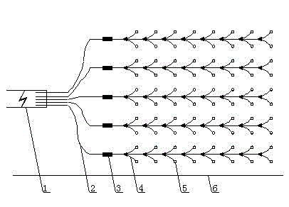
[0013] A non-electrically coupled multi-stage micro-differential initiation network. The detonation network such as figure 1 As shown, it is composed of dry detonating cord 2, hole branch detonating tube 4, blast hole 5 and main millisecond delay detonator 3. A trunk detonating cord 2 is arranged in the middle of every two rows of blastholes 5 on the working face, and each row of blastholes 5 is equipped with a hole branch detonating tube 4, a nonel detonator and a charge bag, and the detonating cord 2 is provided with a dry path. The two blastholes 5 with the cables 2 as symmetrical axes are connected in parallel with the trunk detonating cord 2 clusters through the hole-entry branch detonating tubes 4 in the respective holes. Each trunk detonating cord 2 is connected in parallel with a cluster of excitation devices 1, and each trunk detonating cord 2 is provided with a trunk millisecond delay detonator 3 respectively.

[0014] The delay time of the main millisecond delay d...

Embodiment 2

[0017] A non-electrically coupled multi-stage micro-differential initiation network. The detonation network such as figure 1 As shown, it is composed of dry detonating cord 2, hole branch detonating tube 4, blast hole 5 and main millisecond delay detonator 3. A trunk detonating cord 2 is arranged in the middle of every two rows of blastholes 5 on the working face, and each row of blastholes 5 is equipped with a hole branch detonating tube 4, a nonel detonator and a charge bag, and the detonating cord 2 is provided with a dry path. The two blastholes 5 with the cables 2 as symmetrical axes are connected in parallel with the trunk detonating cord 2 clusters through the hole-entry branch detonating tubes 4 in the respective holes. Each trunk detonating cord 2 is connected in parallel with a cluster of excitation devices 1, and each trunk detonating cord 2 is provided with a trunk millisecond delay detonator 3 respectively.

[0018] The delay time of the main millisecond delay d...

Embodiment 3

[0021] A non-electrically coupled multi-stage micro-differential initiation network. The detonation network such as figure 1 As shown, it is composed of dry detonating cord 2, hole branch detonating tube 4, blast hole 5 and main millisecond delay detonator 3. A trunk detonating cord 2 is arranged in the middle of every two rows of blastholes 5 on the working face, and each row of blastholes 5 is equipped with a hole branch detonating tube 4, a nonel detonator and a charge bag, and the detonating cord 2 is provided with a dry path. The two blastholes 5 with the cables 2 as symmetrical axes are connected in parallel with the trunk detonating cord 2 clusters through the hole-entry branch detonating tubes 4 in the respective holes. Each trunk detonating cord 2 is connected in parallel with a cluster of excitation devices 1, and each trunk detonating cord 2 is provided with a trunk millisecond delay detonator 3 respectively.

[0022] The delay time of the main road millisecond de...


PUM


Abstract

The invention relates to a non-electric coupling multi-section differential detonating circuit. The technical scheme is as follows: a primary circuit detonating cord (2) is arranged between every two rows of blast holes (5) in a working surface; hole inlet branch circuit detonating tubes(4), nonel detonators and cartridge bags are packed into each row of the blast holes (5); two blast holes (5) which take a primary circuit detonating cord (2) as a symmetric axis are in cluster parallel connection with the primary circuit detonating cord (2) through the hole inlet branch circuit detonating tubes(4) in the holes; each primary circuit detonating cord (2) is in cluster parallel connection with a trigger device (1); a primary circuit millisecond delay detonator (3) is arranged on each primary circuit detonating cord (2); each circuit millisecond delay detonator (3) is subjected to differential accumulation according to the delay time of 100-200 ms sequentially; nonel detonators among every 1-3 blast holes (5) are subjected to differential accumulation according to the delay time of 25-50 ms; and the delay time of nonel detonators of two symmetric blast holes (5) which are cluster parallel connection with each primary circuit detonating cord (2) is 25-50 ms. The non-electric coupling multi-section differential detonating circuit has the characteristics as follows: the detonation is reliable, and the detonating circuit is economically feasible.

Description

technical field [0001] The invention belongs to the technical field of differential initiation network, and in particular relates to a non-electrically coupled multi-stage differential initiation network. Background technique [0002] At present, there are two types of non-electric micro-differential detonating networks mainly used in mining or construction earthwork excavation, one is a single detonating tube detonating network and the other is a single detonating cord detonating network. The first type of detonation network adopts a single detonating tube for detonation transmission, and the detonation transmission speed of a single detonation tube is (1950±50) m / s, while the detonation transmission speed of 2# rock explosives commonly used in engineering is greater than or equal to 3200m / s. In the detonation wave transmission process of the differential initiation network, the phenomenon that the detonation wave generated by the first detonating charge will tighten, thin ...

Claims


Application Information

Patent Timeline
Patent Type & Authority Applications(China)
IPC IPC(8): F42B3/10
Inventor 刘艳章王其飞邓磊叶义成柯丽华张丙涛张群赵卫石志军王其虎
Owner WUHAN UNIV OF SCI & TECH
Learn More