
Forecasting method for vehicle body structure-acoustic coupling based on smoothed finite element boundary element method

A technology of boundary element method and prediction method, applied in special data processing applications, instruments, electrical digital data processing, etc., can solve the problem of cost, multi-preprocessing time and manpower, and prediction results are affected by model grid size and calculation frequency Issues such as high and low impact

Inactive Publication Date: 2014-02-05
CHINA AUTOMOTIVE ENG RES INST
View PDF1 Cites 12 Cited by
  • Summary
  • Abstract
  • Description
  • Claims
  • Application Information

AI Technical Summary

Problems solved by technology

However, there are also some problems with this type of method. Regardless of the coupled finite element method and finite element / boundary element method, the structural domain analysis in the structure-acoustic field coupling analysis uses the finite element method, because the finite element method model is too "rigid". , there is a numerical dispersion effect, which causes the prediction results to be greatly affected by the model grid size and the calculation frequency
[0004] In order to meet the reliability of the prediction results of the NVH problem of the car body, engineers need to check the quality of the model during the modeling process, which requires a lot of pre-processing time and manpower. Therefore, it is necessary to propose some new prediction methods to improve the prediction result

Method used


Image

  • Forecasting method for vehicle body structure-acoustic coupling based on smoothed finite element boundary element method
  • Forecasting method for vehicle body structure-acoustic coupling based on smoothed finite element boundary element method
  • Forecasting method for vehicle body structure-acoustic coupling based on smoothed finite element boundary element method

Examples


Embodiment Construction

[0066] Embodiments of the present invention are described in detail below, examples of which are shown in the drawings, wherein the same or similar reference numerals designate the same or similar elements or elements having the same or similar functions throughout. The embodiments described below by referring to the figures are exemplary only for explaining the present invention and should not be construed as limiting the present invention.

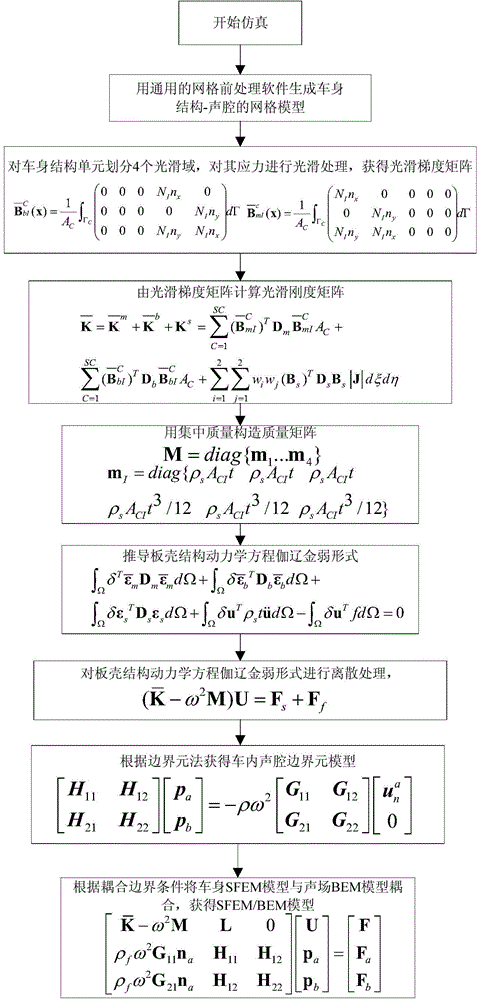
[0067] The present invention provides a method for predicting the acoustic field coupling of vehicle body structure based on the smooth finite element boundary element method, such as figure 1 As shown, the following combination figure 1 The prediction method of the present invention will be described in detail.

[0068] The vehicle body structure sound field coupling prediction method based on smooth finite element boundary element method of the present invention comprises the following steps:

[0069] S1, generating the vehicle body ...


PUM


Abstract

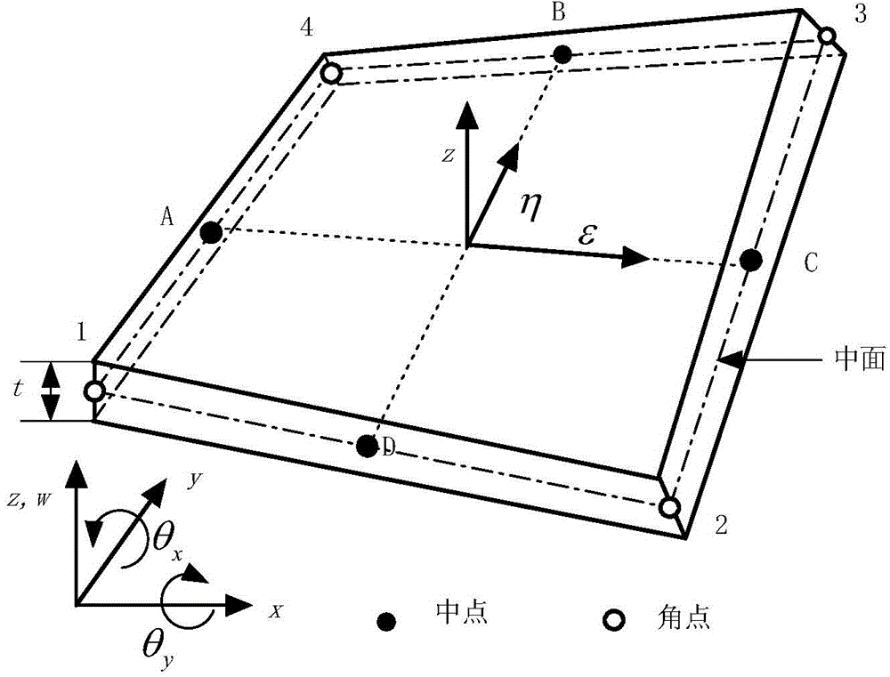
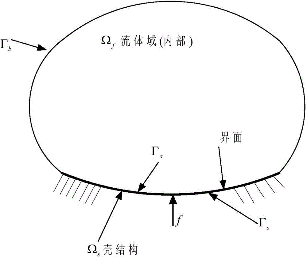
The invention provides a forecasting method for vehicle body structure-acoustic coupling based on a smoothed finite element boundary element method. The method comprises the following steps: generating a vehicle body structure-acoustic grid model; utilizing the smoothed finite element method to perform smooth processing on the stress field in a shell unit; adopting a mixed integral method to perform separate integral of shearing items subjected to shearing strain in the shell under a natural coordinate system; building a smooth Galerkin weak form of a vehicle body shell structure kinetic equation, and obtaining a dynamic equation after the weak form is subjected to discrete processing; creating an acoustic realistic model by using the boundary element method; according to the continuous displacement and pressure of the coupling interface, obtaining a structure-acoustic coupled smoothed finite element boundary element model; performing simulation forecasting by utilizing the coupled model. When the method is used for solving the vehicle body structure-acoustic coupling problem, relatively good calculation effect can be obtained, and the band frequency width can be analyzed more effectively. Moreover, the method has relatively low quality requirements on the model to reduce the pretreatment time, and has a wide engineering application prospect.

Description

technical field [0001] The invention relates to a vehicle body structure-acoustic field coupling prediction method, in particular to a vehicle body structure-sound field coupling prediction method based on a smooth finite element-boundary element method. Background technique [0002] At present, the structure-acoustic field coupling prediction analysis of the vehicle body is an important work in the CAE (computer aided engineering) analysis of the NVH (Noise, Vibration, Harshness, noise, vibration and harshness) performance of the vehicle body. Performance prediction and guidance of NVH performance development are of great significance. [0003] At present, there are analytical methods and numerical methods for vehicle body structure-acoustic field coupling prediction methods, of which analytical methods are generally only for simple problems and models; numerical methods are currently the mainstream prediction methods, including coupled finite element methods and finite ele...

Claims


Application Information

Patent Timeline
IPC IPC(8): G06F17/50
Inventor 姚凌云周建文周舟
Owner CHINA AUTOMOTIVE ENG RES INST
Learn More