AC permanent magnet gain transformation device and voltage regulating and control method thereof

A transformer device, permanent magnet technology, applied in the direction of transformer, AC power input conversion to AC power output, fixed transformer, etc., can solve the problems of loss, power transfer efficiency reduction, etc. The effect of improving power transfer efficiency

Inactive Publication Date: 2014-02-05
戴珊珊
View PDF5 Cites 11 Cited by
  • Summary
  • Abstract
  • Description
  • Claims
  • Application Information

AI Technical Summary

Problems solved by technology

[0002] Electronic transformer is a conventional electronic device with a wide range of applications. It usually plays the role of voltage conversion, circuit isolation protection and impedance matching. The coils and soft magnets of traditional electronic transformers inevitably have losses, which reduce the efficiency of power transfer.

Method used


Image

  • AC permanent magnet gain transformation device and voltage regulating and control method thereof
  • AC permanent magnet gain transformation device and voltage regulating and control method thereof
  • AC permanent magnet gain transformation device and voltage regulating and control method thereof

Examples


Embodiment 1

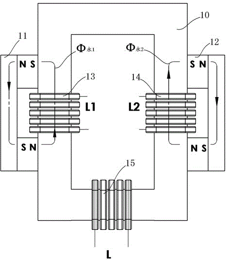
[0033] This embodiment is a transformer with a rectangular closed-loop laminated iron core, and its structure is as follows: figure 1 , 2 , 3 shown.

[0034] The shape of the laminated core 10 in this embodiment is a rectangular closed loop. The primary windings are divided into two groups L1 and L2 and are independent of each other. L1 is wound on the vertical frame on the left side of the rectangular closed loop. The winding method of the primary winding L1 will lead to a unidirectional The direction of the electric excitation magnetic field generated by the pulse current is the same as the direction of the magnetic field generated by the permanent magnet assembly across the primary winding L1, that is, when the current is applied to L1, the laminated iron core above the L1 winding presents S magnetic polarity, and the L1 winding The laminated iron core below presents N magnetic polarity; L2 is wound on the vertical frame on the right side of the rectangular closed loop. Th...

Embodiment 2

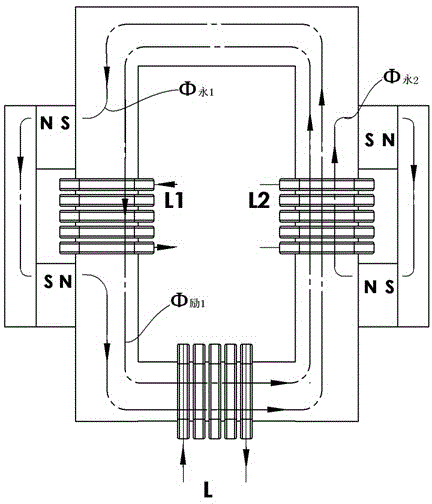
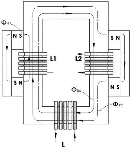
[0043] This embodiment is another kind of transformer with a rectangular closed-loop laminated iron core, and its structure is as follows: Figure 4 with 5 shown.

[0044] In this embodiment, the structural forms of the rectangular closed-loop laminated iron core, primary winding, secondary winding, and permanent magnet assembly are the same as in Embodiment 1, the only difference is that the primary windings L1 and L2 are connected in series, and the winding methods of the primary windings L1 and L2 are The following conditions must be met: when the primary windings L1 and L2 input positive pulse currents, the excitation flux Φ generated by L1 and L2 in the overall magnetic circuit of the laminated iron core 励1 and Φ 励2 It is superimposed in the same direction. When the primary winding L1 and L2 input the reverse pulse current, the excitation flux Φ generated by L1 and L2 in the overall magnetic circuit of the superimposed sheet iron core 励1 and Φ 励2 It is also superimpos...

Embodiment 3

[0050] This embodiment is a transformer with a circular closed-loop laminated iron core, and its structure is as follows: Figure 6-12 shown.

[0051] The laminated iron core 21 of this embodiment is made by laminating several layers of iron-based nano-alloy soft magnetic materials with a thickness of 0.003 mm, and the laminated surface of the laminated iron core is perpendicular to the paper surface. as attached Image 6 As shown, two permanent magnets 20, 26 are respectively arranged at the gaps directly above and directly below the laminated iron core. The N magnetic pole of the upper permanent magnet 20 is close to the clockwise laminated iron core. The S magnetic pole is close to the laminated iron core in the counterclockwise direction, and there is an air gap 27 between the inner surface of the upper permanent magnet 20 and the laminated iron core, while the N magnetic pole of the lower permanent magnet 26 is closely connected to the laminated iron core in the counterc...


PUM

PropertyMeasurementUnit
thicknessaaaaaaaaaa
thicknessaaaaaaaaaa

Abstract

The invention relates to an AC permanent magnet gain transformation device and a voltage regulating and control method thereof. The device adopts the structure that a permanent magnet or a permanent magnet component is additionally arranged in a traditional transformer structure, the magnetic pole face of the permanent magnet is clung to a lamination iron core so as to ensure that inherent permanent magnetic potential of the permanent magnet can be led out under the excitation of excitation current of a primary winding, and is stacked and compounded with the excitation magnetic potential in a closed-loop lamination iron core master magnetic circuit, and as a result, at the output end of the secondary winding, the induced electromotive force stacked by the excitation magnetic flux and the permanent magnet magnetic flux can be inducted. The voltage regulating and control method comprises the following steps: inputting the impulse current of certain amplitude value into the primary winding to ensure that a compounded excitation effect can be generated; changing the pulse count of the impulse current in unit time so as to change and regulate the input and output power of the AC permanent magnet gain transformation device. According to the invention, the power transmission efficiency of the transformation device is further improved, and inherent depletion of the traditional coil winding and the lamination iron core is compensated, and the energy is saved.

Description

technical field [0001] The invention relates to an electronic transformer, in particular to an energy-saving transformer with permanent magnet gain effect and a voltage regulation control method thereof. Background technique [0002] Electronic transformer is a conventional electronic device with a wide range of applications. It usually plays the role of voltage conversion, circuit isolation protection and impedance matching. The coils and soft magnets of traditional electronic transformers inevitably have losses, which reduce the efficiency of power transfer. Contents of the invention [0003] The purpose of the present invention is to increase the permanent magnet in the traditional transformer structure composed of laminated iron core and winding coil, so that the inherent permanent magnet magnetic potential of the permanent magnet and the excitation magnetic potential formed by the excitation current of the primary winding are in the laminated iron core. The total magn...

Claims


Application Information

Patent Timeline
Patent Type & Authority Applications(China)
IPC IPC(8): H01F27/00H01F27/245H01F27/28H02P13/00
CPCH01F27/25H01F27/2823H01F27/2895H01F2003/103H01F30/16G05F3/04H01F27/245
Inventor 戴珊珊朱石柱
Owner 戴珊珊
Why Eureka
Try Eureka