
Low power consumption stand-by circuit of tandem type LED circuit

A LED circuit, low power consumption technology, applied in the direction of lamp circuit layout, electric light source, lighting device, etc., can solve the problems of installation and process difficulties, large power dissipation of parallel regulator tubes, etc., to save radiators, output power The effect of reducing power consumption and reducing power consumption

Inactive Publication Date: 2014-02-05
浙江耀恒光电科技有限公司
View PDF5 Cites 1 Cited by
  • Summary
  • Abstract
  • Description
  • Claims
  • Application Information

AI Technical Summary

Problems solved by technology

The disadvantage of the above technology is: the greater the power of the module, the greater the dissipation power of the shunt regulator tube
The disadvantage of the above technology is: but in order to replace the damaged module voltage and maintain the current of the remaining modules, the power consumption of the backup circuit is still large, so it needs to be equipped with enough radiator and space, and the installation and process are difficult

Method used


Image

  • Low power consumption stand-by circuit of tandem type LED circuit
  • Low power consumption stand-by circuit of tandem type LED circuit

Examples


Embodiment Construction

[0008] The present invention will be further elaborated below through specific embodiments. Examples will help to better understand the present invention, but the present invention is not limited only to the following examples.

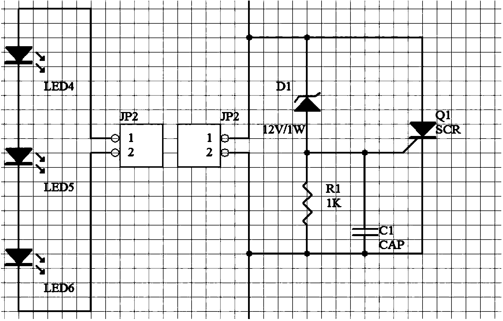
[0009] Such as figure 1 As shown in the low-power backup circuit of this serial LED circuit, the constant current LED driver with wide voltage output is output to this circuit through a cable, and one pole of the voltage regulator is connected to the cathode of the one-way thyristor. The control pole of the thyristor is connected to the other pole of the voltage regulator tube, and the one-way thyristor is connected to the other pole of the voltage regulator tube after connecting the capacitor C1 and the resistor R1 in series and parallel; when the module is in good condition, This circuit is not triggered, it is only used as a backup circuit; when a light source module is open and damaged, the backup circuit is forced to trigger, the voltage regulato...


PUM


Abstract

The invention discloses a low power consumption stand-by circuit of a tandem type LED circuit. A constant current LED driver output by a wide voltage is output to the circuit through a cable, the first electrode of a voltage-regulator tube is connected with the cathode of a one-way silicon controlled rectifier, the control electrode of the one-way silicon controlled rectifier is connected with the other electrode of the voltage-regulator tube, the one-way silicon controlled rectifier is in tandem connection with a capacitor C1 and a resistor R1 and then is connected with the other electrode of the voltage-regulator tube, and the capacitor C1 and the resistor R1 are in parallel connection. When a module is not damaged, the circuit is not triggered, and only used as the stand-by circuit, when an open circuit of a certain light source module is damaged, the stand-by circuit is forced to be triggered, the current flows through the voltage-regulator tube, the one-way silicon controlled rectifier is broken over, and according to internal resistance of the one-way silicon controlled rectifier, the break-over voltage is basically maintained below 1V. The circuit has the advantages that under the constant current, power consumption can be remarkably reduced by the low voltage, a head radiator can be removed, space is reduced, and design is simplified. Meanwhile, for the constant current LED driver output by the wide voltage, the output power consumption is also reduced, and the reduction of the power consumption is beneficial to a driving power source.

Description

technical field [0001] The invention relates to the technical field of LED application, and mainly relates to a low-power backup circuit of a serial LED circuit. Background technique [0002] Prior art: 1. A backup circuit is added at both ends of a single module, and the regulator tubes are directly connected in parallel. After the module is damaged, the regulator tube replaces the module so that the remaining light source modules can continue to work. The disadvantage of the above technology is: the greater the power of the module, the greater the dissipation power of the shunt regulator tube. Power type Zener tubes are expensive and difficult to use. 2. The combination of power transistor and low-power voltage regulator can reduce the cost. The disadvantages of the above technology are: but to replace the damaged module voltage and maintain the current of the remaining modules, the power consumption of the backup circuit is still large, so it needs to be equipped with ...

Claims


Application Information

Patent Timeline
Patent Type & Authority Applications(China)
IPC IPC(8): H05B37/00
Inventor 吕健郭军华任金松范世权
Owner 浙江耀恒光电科技有限公司
Learn More