Method and apparatus for antenna radiation cross polar suppression
A cross-coupling, antenna array technology, applied in the field of cellular communication, can solve problems such as XPD difficult optimization practice
- Summary
- Abstract
- Description
- Claims
- Application Information
AI Technical Summary
Problems solved by technology
Method used
Image
Examples
Embodiment 1
[0036] Example 1: Cross-coupling imposed between base station and antenna:
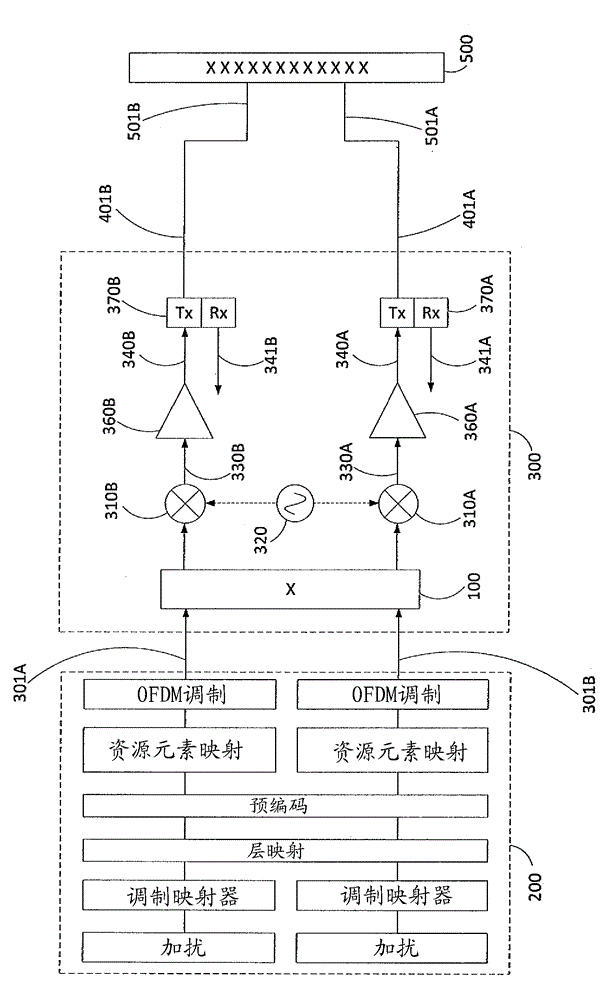
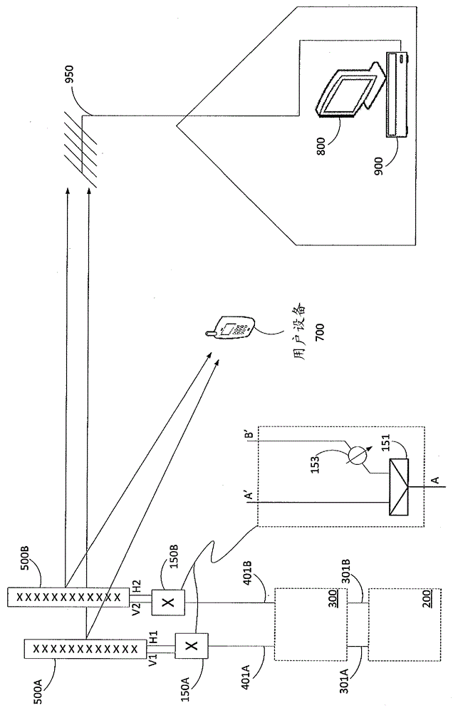
[0037] image 3 A cellular radio base station comprising a baseband processing section (200) and an RF processing section (300) is illustrated with two antenna RF ports (401A, 401B). image 3 Also illustrated is an antenna array 500 with antenna connection ports (501A, 501B) of the X-polarized antenna array. In one embodiment, as in image 3 Schematically shown in , after the base station modules (eg, the baseband processing section 200 of the base station and the RF processing section 300 of the base station) and before connecting to the X-polarized antenna (500) in the base station configuration is applied as above in figure 1 The cross-coupling function or module (100) shown in, therefore, the cross-coupling network is tuned / designed to maximize XPD over a predetermined or most significant range of azimuth, electrical inclination and frequency. It should be noted that the base station modules or...
Embodiment 2
[0039] Example 2: Cross-coupling imposed between power amplifier and duplex;
[0040] In another embodiment, as in Figure 4 As schematically shown in , after the power amplifiers (360A, 360B) but before any Tx / Rx duplex stages (370A, 370B) within the base station RF section (300) are applied as above in figure 1The cross-coupling network (100) shown in . In this embodiment, independent Tx and Rx path cross-coupling networks can be implemented. Transmit and receive RF channels in a frequency division duplex (FDD) base station system are commonly Tx / Rx duplexed (370A, 370B) within the base station RF section (300), where the Tx and Rx channels can be frequency-duplexed. are significantly separated and will result in different antenna XPD characteristics for Tx and Rx frequencies. This embodiment allows independent cross-coupling networks and tuning for the Tx and Rx paths. For clarity, Figure 4 Only the cross-coupling network applied in the Tx path is shown. However, a s...
Embodiment 3
[0041] Example 3: Cross-coupling imposed between base station and antenna using directional coupling devices:
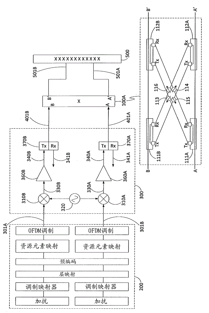
[0042] as in Figure 5 Yet another embodiment, schematically shown in , uses a cross-coupling network (100A) with directional power coupling devices (111A, 112A, 111B, 112B) to perform the power splitting and recombining functions of the cross-coupling network. This cross-coupling network (100A) is figure 1 An alternative embodiment of the cross-coupling network (100). Transmit and receive RF channels in frequency division duplex (FDD) base station systems are commonly Tx / Rx duplexed within the base station, where the Tx and Rx channels can be significantly separated in frequency and will result in Different antenna XPD characteristics for Rx frequencies. This embodiment allows independent cross-coupling networks and tuning for the Tx and Rx paths. In other words, two cross-coupling networks can be applied, wherein both cross-coupling networks share the same spli...
PUM
 Abstract
Description
Claims
Application Information
 - R&D
- Intellectual Property
- Life Sciences
- Materials
- Tech Scout
- Unparalleled Data Quality
- Higher Quality Content
- 60% Fewer Hallucinations
Browse by: Latest US Patents, China's latest patents, Technical Efficacy Thesaurus, Application Domain, Technology Topic, Popular Technical Reports.
© 2025 PatSnap. All rights reserved.Legal|Privacy policy|Modern Slavery Act Transparency Statement|Sitemap|About US| Contact US: help@patsnap.com


