Pluggable system and optical transceiver applicable to pluggable system

An optical transceiver and plug-in technology, which is applied in electromagnetic transceivers, instruments, optics, etc., can solve problems such as poor communication quality and insufficient connector coordination, and achieve the effect of reducing thrust

Inactive Publication Date: 2014-02-05
SUMITOMO ELECTRIC IND LTD
View PDF8 Cites 5 Cited by
  • Summary
  • Abstract
  • Description
  • Claims
  • Application Information

AI Technical Summary

Problems solved by technology

Less force applied to the optical transceiver may result in an insufficient mating between the two connectors, potentially resulting in poor communication between the optical transceiver and the host system

Method used


Image

  • Pluggable system and optical transceiver applicable to pluggable system
  • Pluggable system and optical transceiver applicable to pluggable system
  • Pluggable system and optical transceiver applicable to pluggable system

Examples


no. 1 example

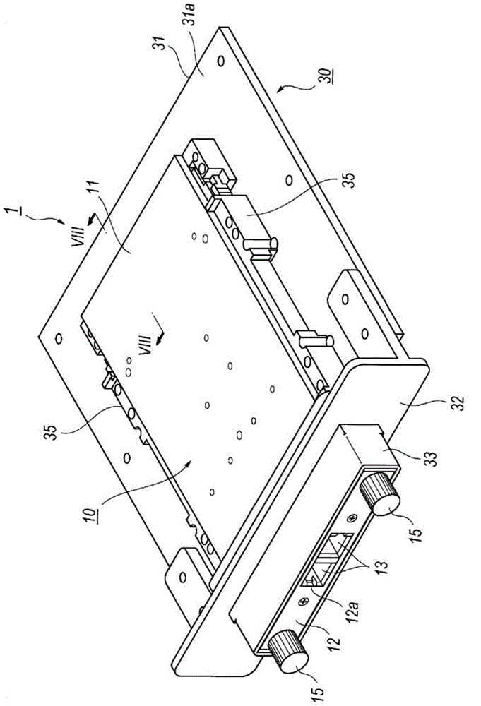
[0037] figure 1 is a perspective view of a plug-in system 1 comprising an optical transceiver 10 and a host system 30 according to a first embodiment of the present invention. The optical transceiver 10 belongs to a so-called plug-in optical transceiver conforming to the CFP standard.

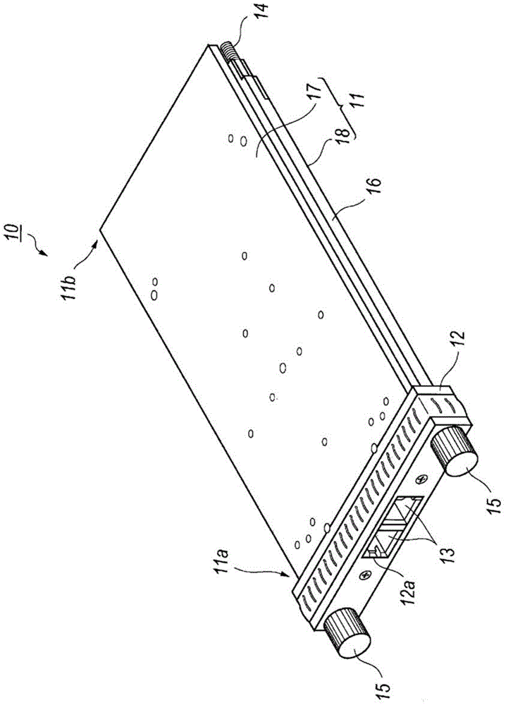
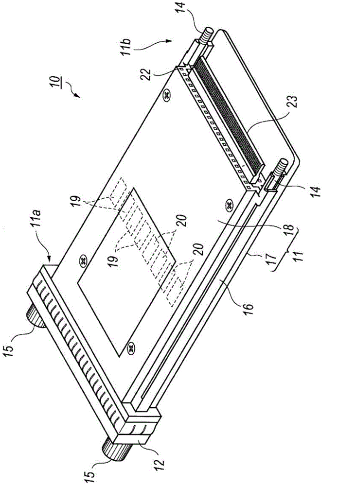
[0038] figure 2 It is a perspective view of the time transceiver 10 seen from the front top, image 3 The optical transceiver 10 is shown as viewed from the rear and below. Such as figure 2 and image 3 As shown, the optical transceiver 10 includes a housing 11 and a front cover 12 , and the front cover 12 is attached to the front end 11 a of the housing 10 . From the standpoint of heat dissipation and casting performance, the housing 11 may be made of, for example, aluminum or zinc.

[0039]In the following description, it is assumed that "front" refers to the side where the front cover 12 is fitted and "rear" refers to the other side where the electrical plug 23 is provided, for illus...

no. 2 example

[0054] A plug-in system including an optical transceiver and a host connector cover according to a second embodiment of the present invention will be described below. Figure 13 A plug-in system of a second embodiment is shown, wherein a plug-in system 1A includes an optical transceiver 10A and a host system 30A.

[0055] Figure 14 is a perspective view of the rear of the optical transceiver 10A; the optical transceiver 10A is provided with a rear 22A instead of the rear 22 of the previous embodiments. Other arrangements of the optical transceiver 10A are the same as those of the aforementioned optical transceiver 10 . The rear portion 22A is substantially flat, that is to say, the difference between the rear portion 22A of this embodiment and the previous embodiment may be that: the rear portion 22A is not provided with the concave portion 11A or the convex portion A21.

[0056] Figure 15 is showing Figure 13 A perspective view of host system 30A is shown. The differe...


PUM


Abstract

An optical transceiver and a pluggable system to enhance the reliability of the communication between the optical transceiver and the host system are disclosed. The rear of the housing of the transceiver provides a periodic structure, a plurality of hollows or a plurality of projections, arranged along the gasket provided in the host connector. Only portions of the periodic structure come in contact with the gasket, and the repulsive force caused by the gasket is consequently weakened to enhance the reliability of the mating of the plug in the optical transceiver with the host connector. The width of the hollows, or the pitch of the projections is set to be shorter than a quarter wavelength of a signal transmitted between the transceiver and the host system to reduce the EMI radiation leaking from the end of the transceiver.

Description

technical field [0001] The present invention relates to a plug-in system for an optical transceiver comprising a plug-in optical transceiver and a host connector cover of the host connector. Background technique [0002] Various plug-in systems for optical transceivers and host connectors have been disclosed in the prior art. For example, US Patent No. 7,710,734 discloses a platform including plug-in optoelectronic components and a host system on which the optoelectronic components are installed. The optoelectronic assembly includes: a circuit board mounted with optical elements and electrical elements; a case encapsulating the circuit board inside; and an electrical plug electrically connected to the circuit board and protruding from the rear of the case. The host system includes: a host connector, which will mate with the electrical plug; and a host connector cover, which covers the host connector. The front portion of the host connector cover is provided with an opening...

Claims


Application Information

Patent Timeline
Patent Type & Authority Applications(China)
IPC IPC(8): H01R13/6583G02B6/42H04B10/2507H04B10/40H04B10/43H04B10/50H04B10/60
CPCG02B6/4284G02B6/4277G02B6/4261H01R13/5219H01R13/658
Inventor 冲和重
Owner SUMITOMO ELECTRIC IND LTD
Why Eureka
Try Eureka