A welding method for mounting frame

A mounting frame and welding technology, which is applied in the field of mechanical processing, can solve the problems of large calibration workload, inability to correct, and reduce processing efficiency, so as to shorten the calibration work, ensure straightness and local flatness requirements, and improve one-time qualification rate effect

Active Publication Date: 2016-01-20
WUHAN MARINE MACHINERY PLANT
View PDF4 Cites 0 Cited by
  • Summary
  • Abstract
  • Description
  • Claims
  • Application Information

AI Technical Summary

Problems solved by technology

[0004] In the process of realizing the present invention, the inventor found that there are at least the following problems in the prior art: because the length of the installed pry steel plate is generally 11-15m, and the width is 800-900mm, which is a slender part, there are 7 other parts with a diameter of 600mm on the surface -700mm installation hole, the diameter of the hole is more than half the width of the installation pry plate, so the rigidity is very poor. If the installation pry plate is CNC cut and formed at one time before the structural parts of the installation frame are made, it is easy to be welded in the subsequent installation frame. In particular, during the welding of the installation pry plate and the K-type plate, the installation pry plate is wave-shaped and deformed, which makes it impossible to correct and affects the flatness and straightness of the mounting frame, or the calibration workload is very large, which reduces the processing efficiency

Method used


Image

  • A welding method for mounting frame
  • A welding method for mounting frame
  • A welding method for mounting frame

Examples


Embodiment Construction

[0044] In order to make the object, technical solution and advantages of the present invention clearer, the implementation manner of the present invention will be further described in detail below in conjunction with the accompanying drawings.

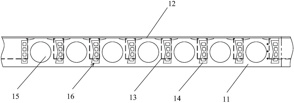
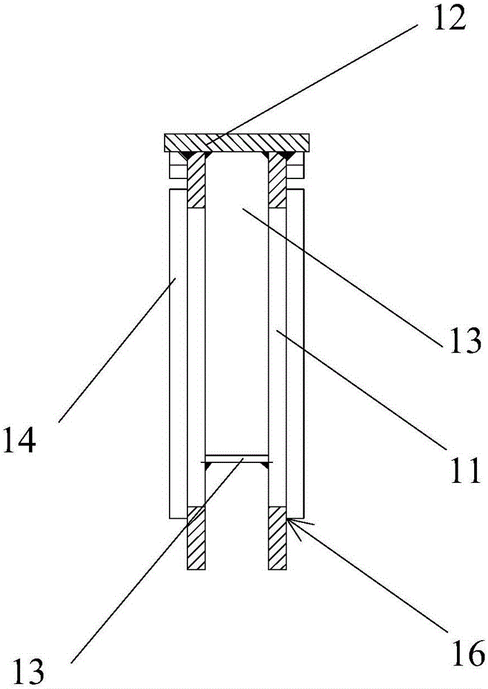
[0045] The mounting frame is a key part of the lifting mechanism of the jack-up drilling platform, see figure 1 and figure 2 , The mounting frame is composed of two prying steel plates 11, a back plate 12, some U-shaped rib plates 13, and a K-shaped plate 14. Wherein, a plurality of installation holes 15 are cut on each installation skid plate 11 . The two installation skid plates 11 are arranged opposite to each other along the length direction, the back plate 12 is welded on the two installation skid plates 11 along the length direction of the installation skid plates 11, the back plate 12 and the two installation skid plates 11 form a concave structure, U-shaped Rib plate 13 is welded between two pieces of skid steel plates 11, a...


PUM

PropertyMeasurementUnit
lengthaaaaaaaaaa
widthaaaaaaaaaa

Abstract

The invention discloses a mounting rack assembling and welding method and belongs to the field of machining. The method comprises the steps of respectively preparing and forming mounting two mounting prying steel plate blanks, a backboard, a plurality of K-shaped plates and U-shaped rib plates; assembling and welding the K-shaped plates on the mounting prying steel plate blanks, assembling and welding one U-shaped rib plate between the two mounting prying steel plate blanks; assembling and welding the two mounting prying steel plate blanks on the backboard; cutting mounting holes in each mounting prying steel plate blank to obtain the mounting rack. The mounting holes are cut in the mounting prying steel plate blanks after the mounting rack is formed, the deformation problem during the subsequent welding of the mounting rack after the preparation cutting of slender parts is solved, the correction time after the formation of the mounting rack is greatly shortened, or the correction is not needed, the one-time pass rate of products is improved, and the requirements on the straightness and local flatness of the mounting rack are met.

Description

technical field [0001] The invention relates to the field of mechanical processing, in particular to a welding method for a mounting frame. Background technique [0002] Jack-up drilling platform is mainly composed of platform, legs and lifting mechanism. The lifting mechanism includes a mounting frame and a lifting drive unit. The mounting frame is respectively welded to the guide column of the pile leg and the deck of the platform, and the lifting drive unit is installed on the mounting frame. [0003] Since the lifting drive unit provides the lifting force for the platform to rise along the legs, and the mounting frame is the main bearer of the lifting force, the requirements for flatness and straightness of the mounting frame are extremely high. The welding method of the mounting frame determines the flatness and straightness of the mounting frame. The existing welding method is usually to install and weld each structural part of the mounting frame separately, includi...

Claims


Application Information

Patent Timeline
Patent Type & Authority Patents(China)
IPC IPC(8): B23P15/00B23K31/02
CPCB23K31/02B23K2101/18B23P15/00
Inventor 程文池杨新明姜志龙郑夏王法斌
Owner WUHAN MARINE MACHINERY PLANT
Why Eureka
Try Eureka