
Shaft cutting tool edge grinder

A technology for cutting tools and sharpening machines, which is applied to the parts of grinding machine tools, manufacturing tools, and grinding drives, etc., can solve the problems of tool sharpening, tool scrapping, uneven grinding edges, etc., to improve work efficiency. , The effect of saving tool cost and small body design

Inactive Publication Date: 2014-02-12
JINGJIANG CHANGYUAN HYDRAULIC MACHINERY
View PDF8 Cites 8 Cited by
  • Summary
  • Abstract
  • Description
  • Claims
  • Application Information

AI Technical Summary

Problems solved by technology

[0003] Shaft-type rotary cutting tools, such as end mills, ball end mills, twist drills and carving knives, are widely used, not only in mechanical processing, but also in construction, decoration, electronics and other industries. Traditional Grinding shaft rotary cutting tools such as ball end milling cutters, twist drills or carving knives are generally obtained by manual operation based on the experience of operators, but there are phenomena of uneven grinding edges and asymmetrical two-way end face margins, which affect to machining accuracy and work efficiency
Especially the ball-end cutters currently used in CNC machine tool processing, due to the poor precision of the sharpening equipment, the cutting tools are frequently sharpened due to cutting wear, which directly affects the processing efficiency and quality, or the tools can only be scrapped in advance, resulting in waste
[0004] Although there are special sharpening equipment for knives, the professional nature requires professional technicians to operate, high cost and high expenses, and most processing companies are difficult to accept, such as Chinese patents ZL94245769.2, 200910221826.X, 201020112285.5, etc. Patented technical solution, but the actual working state has not reached the multi-purpose performance and processing accuracy described in the technique, or the operation process is too complicated and difficult to operate, so the current equipment that can grind shaft-type rotary cutting tools needs to be improved

Method used


Image

  • Shaft cutting tool edge grinder
  • Shaft cutting tool edge grinder

Examples


Embodiment Construction

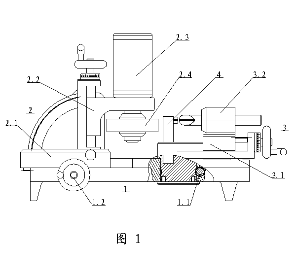
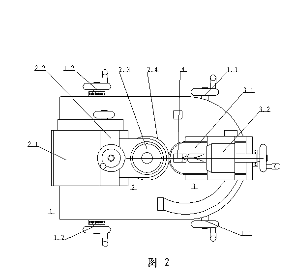
[0014] Embodiment ﹙The carriages appearing below are all constructed with a dovetail groove type combination of a seat body and a carriage with a plug iron sliding fit, including a screw nut drive, a dial and a tightening device, a hand wheel, etc. The structure is well-known Technology, not detailed, or not shown in the drawings.:

[0015] A shaft-type cutting tool sharpening machine, connected by the seat plate 1 and the seat plate 1, by the rotating worm 1.1, the feed drive shaft 1.2, the translation carriage 2.1, the vertical tilting carriage 2.2, the motor 2.3, The grinding wheel 2.4 and the grinding assembly 2 consist of the tool feed assembly consisting of the journal deflection carriage 3.1, the tool clamping head 3.2, and the tool setter 4.

[0016] The middle part of the seat plate 1 is provided with a shaft through hole. The deep middle part of the through hole crosses the waist of the seat plate and is connected to a worm 1.1, and each hand wheel connected at the two en...


PUM


Abstract

The invention relates to a shaft cutting tool edge grinder which comprises a base plate, a grinding assembly and a tool feeding assembly. The grinding assembly is connected onto the base plate and comprises a translation towing platform, a vertical inclinable carriage, a motor and a grinding wheel, the tool feeding assembly comprises an eccentric journal rotating carriage combination, a tool clamping head and a tool setter, the motor on the vertical inclinable carriage on the translation towing platform drives the grinding wheel to run, front and back parallel movement and up and down height adjustment of the grinding wheel are realized along with the inclinable carriage tilting by maximum 90-degree angles, and a journal deflection carriage matched with the tool feeding assembly is moved in a circulating manner by a worm drive journal deflection carriage to grind the edge of a shaft cutting tool by taking a shaft through hole in a vertical rotating shaft connecting seat plate on the journal deflection carriage and by taking opposite 90-degree arc track projecting layers on the seat plate as rotating strokes. The shaft cutting tool edge grinder is small in size, simple to operate, accurate and rapid, and can easily grind the shaft rotary-cutting tool without profession.

Description

Technical field [0001] The invention relates to a small grinding device that is simple to operate, accurate and fast, and can easily grind shaft-type rotary cutting machine tools, such as ball-end milling cutters, twist drills or engraving knives, without special expertise, in particular to a shaft-type cutting Tool sharpening machine. [0002] Background technique [0003] Shaft-type rotary cutting tools, such as end mills, ball end mills, twist drills and engraving knives, are widely used. They are not only used in mechanical processing, construction, decoration, electronics and other industries. The traditional Grinding shaft rotary cutting tools such as ball end milling cutters and twist drills or engraving knives are generally obtained manually based on the experience of the operator, but there are uneven grinding edges and asymmetrical two-way end faces, which affects To processing accuracy and work efficiency. Especially the current ball-end tools used in CNC machine tool...

Claims


Application Information

Patent Timeline
Patent Type & Authority Applications(China)
IPC IPC(8): B24B3/00
CPCB24B3/00B24B47/20
Inventor 李国水
Owner JINGJIANG CHANGYUAN HYDRAULIC MACHINERY
Learn More