
Device and method for heat distribution in motor vehicle

A heat distribution technology for motor vehicles, applied to motor vehicles, engine-driven traction, electrical devices, etc., can solve problems such as not being disclosed, and achieve the effect of reducing high voltage

Active Publication Date: 2014-02-12
HANON SYST
View PDF9 Cites 17 Cited by
  • Summary
  • Abstract
  • Description
  • Claims
  • Application Information

AI Technical Summary

Problems solved by technology

[0009] The use of not only the internal combustion engine but also the electric motor in a common system as heat sink and / or heat source as required and the integration of the prime mover in the thermal management unit in the air conditioning system of the passenger compartment is not known in the prior art

Method used


Image

  • Device and method for heat distribution in motor vehicle
  • Device and method for heat distribution in motor vehicle
  • Device and method for heat distribution in motor vehicle

Examples


Embodiment Construction

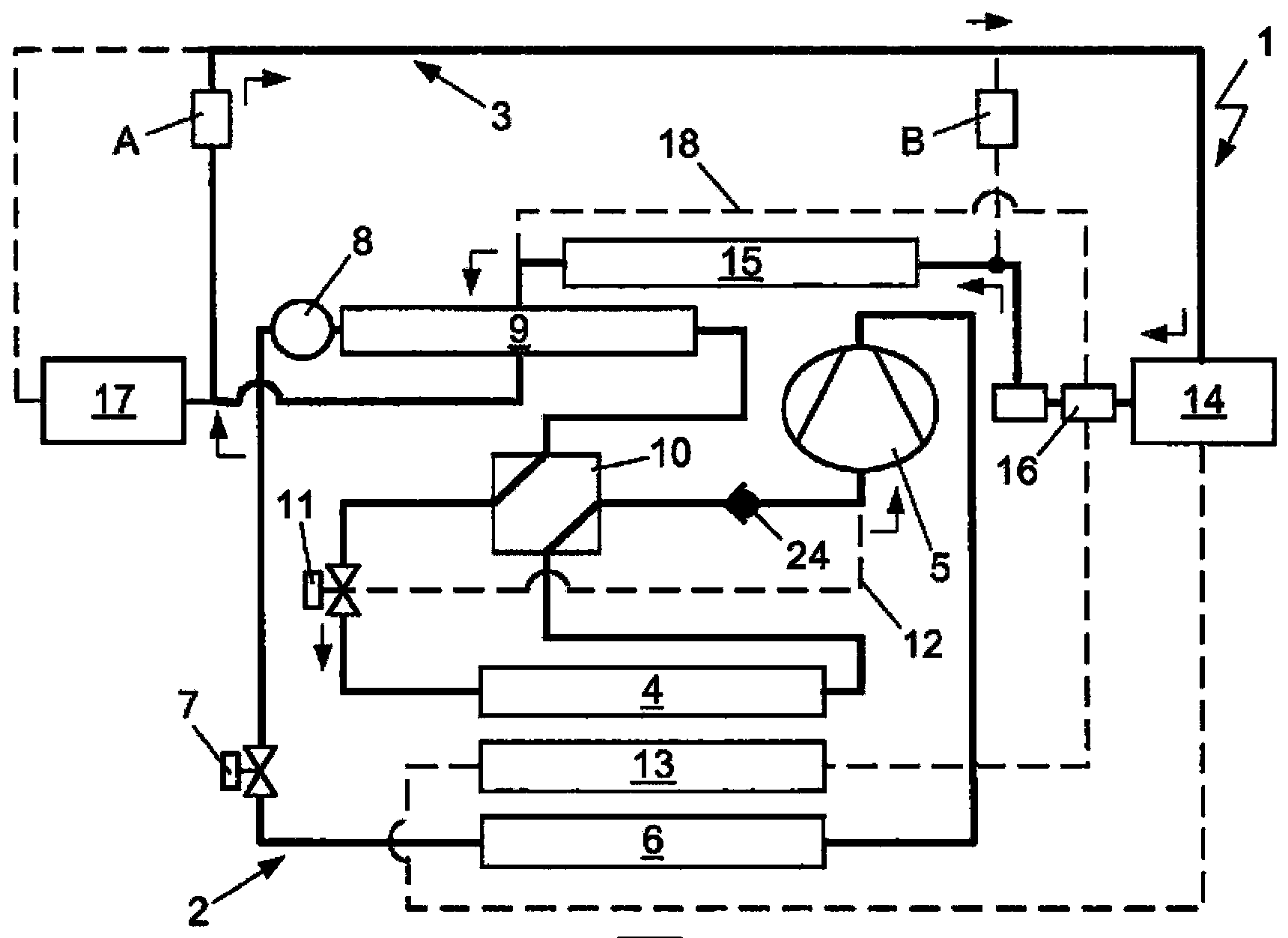
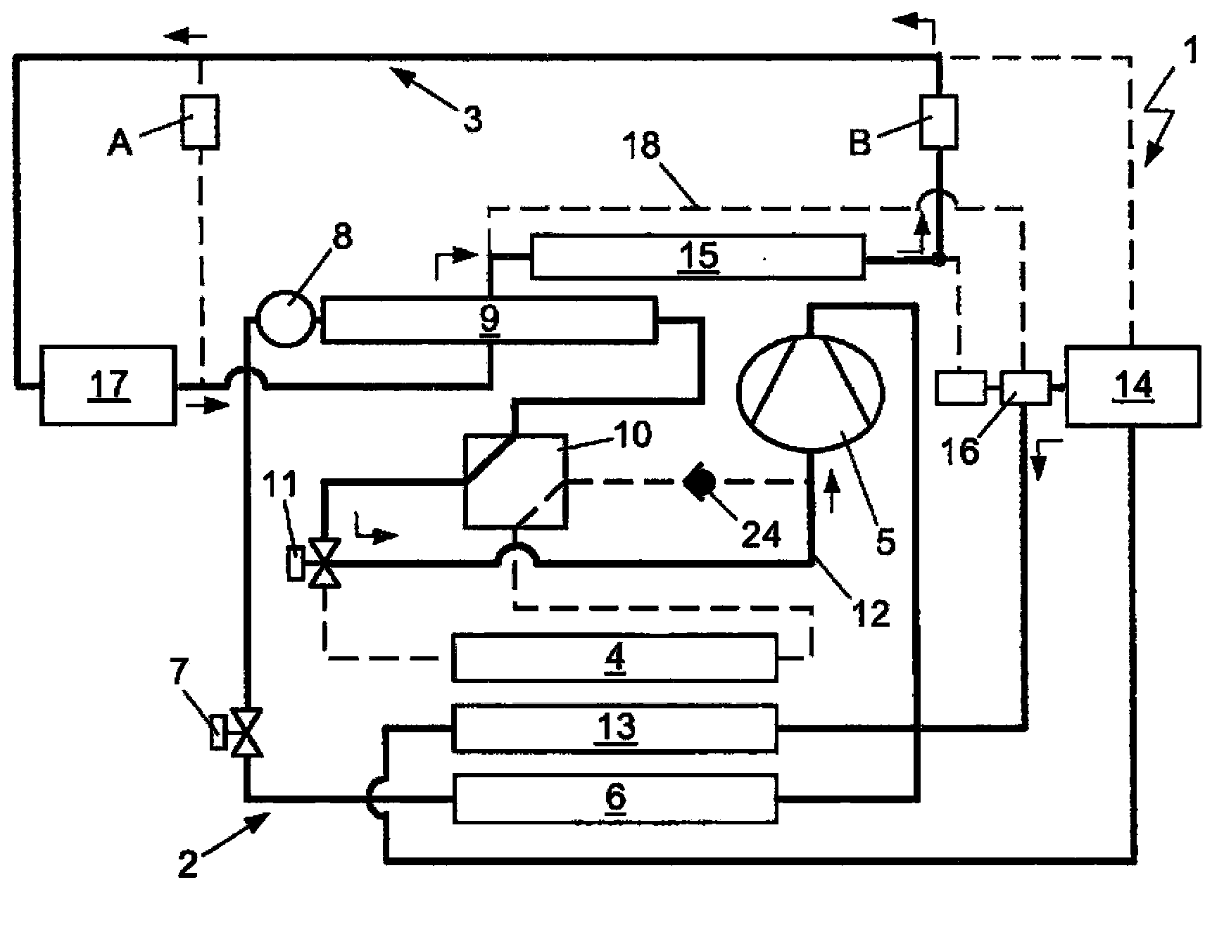
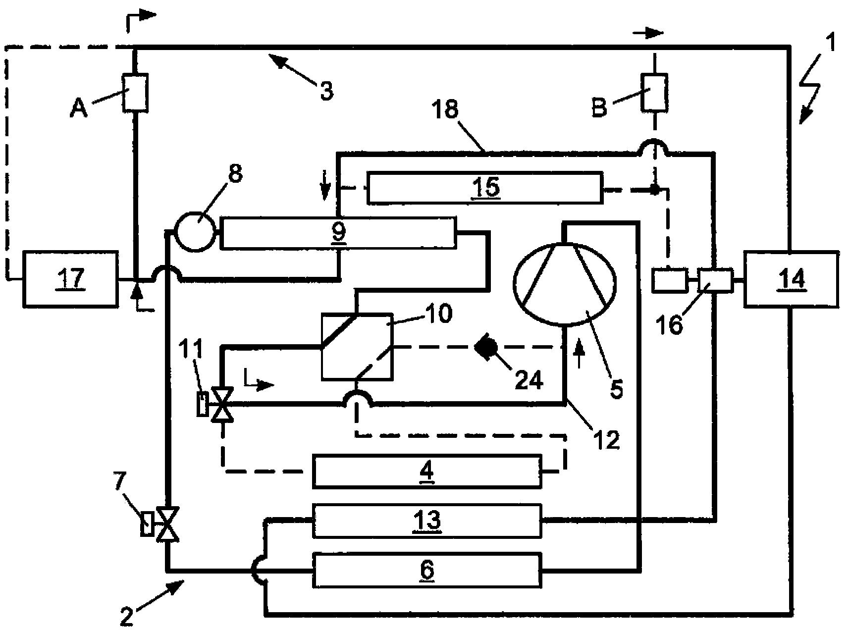
[0038] in Figure 1a to Figure 1e In, the device 1 for a motor vehicle having a refrigerant circuit 2 and a combined prime mover cooling circuit 3 is shown in different operating modes, the prime mover cooling circuit is used to regulate the first prime mover 14 configured as an internal combustion engine and the structure The second prime mover of the electric motor17. The pipe routes in operation of the refrigerant circuit 2 or the prime mover cooling circuit 3 are shown in solid lines, while the pipe routes that are not in operation are shown by dashed lines. The flow direction of the fluid is indicated by means of arrows.

[0039] Refrigerant circuit 2 except Figure 1a The evaporator 4, the compressor 5, and the heat exchanger 6 operating as a heating recorder (which also serve as a second condenser or a second condenser) are successively arranged in the flow direction of the refrigerant in the refrigeration system mode or the reheating mode shown in A heat pump condenser is...


PUM


Abstract

A device and method for heat distribution in a hybrid motor vehicle are provided. The device includes an engine cooling circuit; and a refrigerant circuit for a combined operation in a refrigeration heat pump mode and a reheating mode, includes an evaporator, a compressor, a heat exchanger to supply heat from the refrigerant to air being conditioned for a passenger compartment; and a heat exchanger to transfer heat between a refrigerant of the refrigerant circuit and coolant of the engine cooling circuit, wherein the heat exchanger operates as an evaporator for the heat transfer, and as a condenser for the heat transfer from the condensing refrigerant to the coolant. The engine cooling circuit is provided with a first engine and a second engine. The first engine is configured as an internal combustion engine, and the second engine is configured as a motor. The invention also relates to a method for operating a device for heat distribution of the motor vehicle.

Description

Technical field [0001] The present invention relates to a device for heat distribution in a motor vehicle, especially a hybrid vehicle, which has a prime mover cooling circuit and a refrigerant circuit, the refrigerant circuit is configured to operate in a combination of a refrigeration system mode and a heat pump mode and Used in reheating mode. The refrigerant circuit has an evaporator, a compressor, a heat exchanger for supplying heat from the refrigerant to the air for the passenger compartment to be conditioned, and a coolant for the refrigerant in the refrigerant circuit and the prime mover cooling circuit A heat exchanger for heat transfer between. Furthermore, the invention relates to a method for operating this device. Background technique [0002] Motor vehicles with different drive systems are known from the prior art. The concept is based on a hybrid drive by means of an internal combustion engine, an electric motor or two types of prime movers. In a hybrid vehicl...

Claims


Application Information

Patent Timeline
IPC IPC(8): B60H1/00
CPCB60H2001/00949F25B2400/0409F25B13/00F25B49/02F25B9/008B60H2001/00935F25B2400/0417F25B40/00B60H1/00907F25B6/04F25B2600/2501B60H2001/00928F25B2341/0662F25B2400/0419B60L1/003B60L3/0023B60L3/0061B60L2240/34B60L2240/36B60L2240/425B60L2270/46B60L50/16Y10S903/904Y02T10/64Y02T10/7072F25B41/39Y02T10/70B60H1/00385B60H2001/00307B60K6/22B60K11/02B60Y2200/91B60Y2200/92B60Y2306/05
Inventor P·赫尔
Owner HANON SYST
Learn More