
Composite electromagnetic wave transmission and measurement while drilling device

A technology of measuring while drilling and measuring devices, which is applied in the direction of construction, etc., can solve the problems of limiting signal transmission distance, affecting the promotion and application of electromagnetic wave instruments, and limiting the transmission distance of electromagnetic waves, etc., and achieves the effects of fast transmission speed, reasonable structure, and increased measurement depth

Active Publication Date: 2014-02-12
BC P INC CHINA NAT PETROLEUM CORP +1
View PDF7 Cites 3 Cited by
  • Summary
  • Abstract
  • Description
  • Claims
  • Application Information

AI Technical Summary

Problems solved by technology

[0002]In oil drilling directional well construction, electromagnetic wave measurement-while-drilling instruments are often used for directional operations. The weakness of the medium, however, because the transmission of electromagnetic wave signals is greatly affected by the resistance of the bottom layer, the transmission distance of electromagnetic waves is limited, and the measuring unit (gamma short joint and probe tube) of the electromagnetic wave instrument currently used is connected with the transmitting unit Yes, the signal is uploaded from the measurement depth, which limits the transmission distance of the signal, thus affecting the promotion and application of electromagnetic wave instruments

Method used


Image

  • Composite electromagnetic wave transmission and measurement while drilling device
  • Composite electromagnetic wave transmission and measurement while drilling device
  • Composite electromagnetic wave transmission and measurement while drilling device

Examples


Embodiment Construction

[0018] The present invention is not limited by the following examples, and specific implementation methods can be determined according to the technical solutions of the present invention and actual conditions.

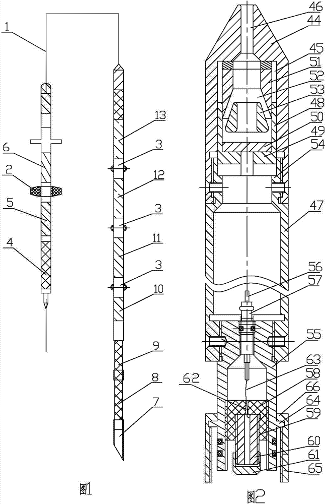
[0019] In the present invention, for the convenience of description, the description of the relative positional relationship of each component is based on the figure 1 For example, the positional relationship of top, bottom, left, right, etc. is determined according to the layout direction of the drawings in the specification.

[0020] Below in conjunction with embodiment and accompanying drawing, the present invention will be further described:

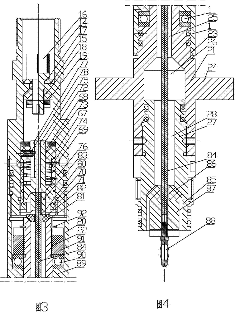
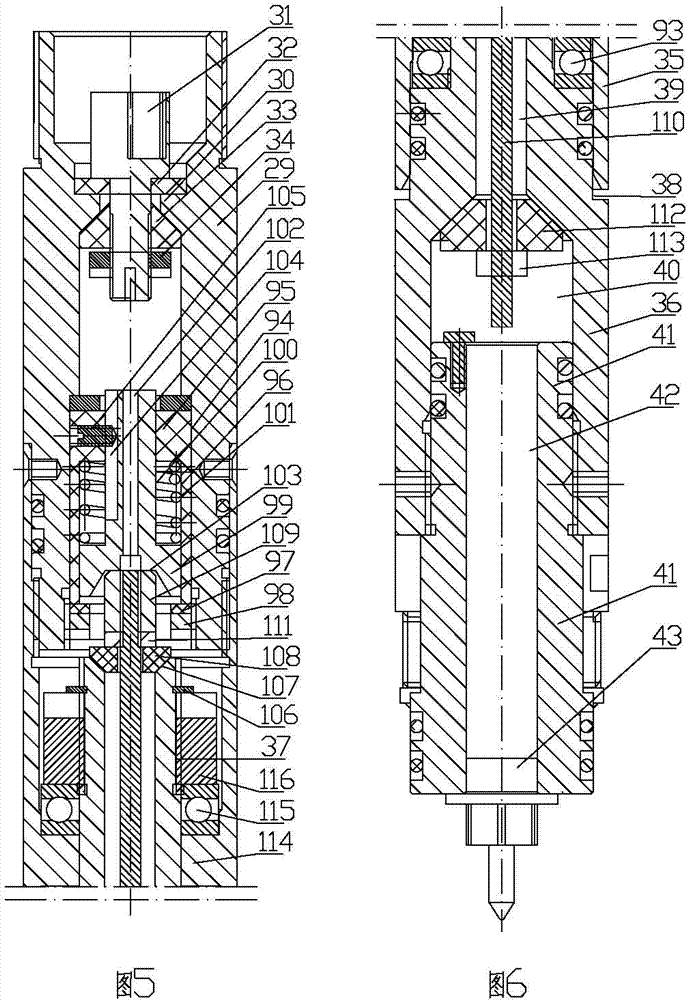
[0021] as attached figure 1 As shown, the composite electromagnetic wave transmission measurement-while-drilling device includes a signal relay transmitting device, a lower instrument measuring device and a cable 1; A transmitting cable head is installed, and a transmitting centralizer 2 is fixedly installed on th...


PUM


Abstract

The invention relates to petroleum drilling directional well signal transmission and measurement devices and provides a composite electromagnetic wave transmission and measurement while drilling device. The composite electromagnetic wave transmission and measurement while drilling device comprises a signal relay transmission device, a lower part instrument measurement device and a cable, wherein a crossed rotary pup joint is fixedly mounted at the upper end of the signal relay transmission device; a transmission cable head is fixedly mounted at the upper end of the crossed rotary pup joint; a transmission centering device is fixedly mounted on the signal relay transmission device. The composite electromagnetic wave transmission and measurement while drilling device is reasonable and compact in structure and convenient to use, can prevent the cable from being twisted off through the crossed rotary pup joint and the rotary pup joint during use, can overcome the problem that the transmission distance of an electromagnetic wave signal is limited in a bottom layer, and can increase the measurement depth of an electromagnetic wave instrument; the transmission data amount is large and the transmission speed is high when the signal is transmitted by the cable, and the measurement efficiency is not influenced; in the signal transmission process, the cable can be effectively prevented from being twisted and damaged.

Description

technical field [0001] The invention relates to an oil drilling directional well signal transmission measuring device, which is a composite electromagnetic wave transmission measuring device while drilling. Background technique [0002] In oil drilling directional well construction, electromagnetic wave measurement while drilling is often used for directional operations. This instrument transmits signals through electromagnetic waves, which overcomes the weakness that mud pulse transmission signals require liquid media. However, the transmission of electromagnetic wave signals is limited by the resistance of the bottom layer. The impact is relatively large, which limits the transmission distance of electromagnetic waves. However, the measuring unit (gamma subsection and probe tube) of the electromagnetic wave instrument currently used is connected with the transmitting unit, and the signal is uploaded from the measurement depth, which limits the transmission distance of the s...

Claims


Application Information

Patent Timeline
Patent Type & Authority Applications(China)
IPC IPC(8): E21B47/13
Inventor 邹和均李俊胜王建毅葛娜张仪
Owner BC P INC CHINA NAT PETROLEUM CORP
Learn More