An electronic expansion valve

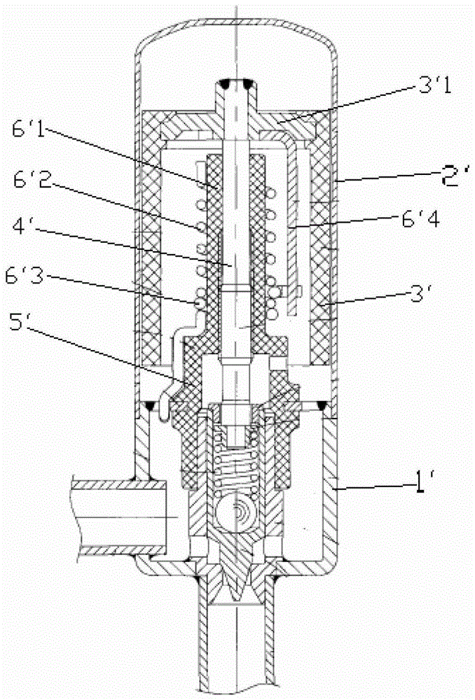
An electronic expansion valve, valve seat technology, applied in valve details, valve device, valve operation/release device, etc., can solve the problem of low connection reliability of stop rod 6'4, large radial size of magnet 3', stop The problems such as the falling off of the moving rod 6'4 can achieve the effect of realizing the miniaturization of the product, simplifying the assembly process and reducing the radial size.

Active Publication Date: 2017-03-01
ZHEJIANG SANHUA INTELLIGENT CONTROLS CO LTD
View PDF5 Cites 0 Cited by
  • Summary
  • Abstract
  • Description
  • Claims
  • Application Information

AI Technical Summary

Problems solved by technology

[0007] First, the stop rod 6'4 is connected to the inner wall of the connecting seat 3'1, and because it is assembled inside the magnet 3', the assembly process is more difficult and the assembly cost is higher; in addition, the stop rod 6'4 The reliability of the connection is also low. After working for a period of time, the stop rod 6'4 is prone to fall off;
[0008] Second, in order to cooperate with the stop rod 6'4, the protruding part 6'3a of the slip ring 6'3 needs to protrude a sufficient length in the radial direction, and at the same time, it must be considered that it cannot be in contact with the inner wall of the magnet 3'. Interference occurs, so the magnet 3' is required to have a larger radial dimension, which increases the material cost on the one hand, and is not conducive to the miniaturization of the product on the other hand

Method used


Image

  • An electronic expansion valve
  • An electronic expansion valve
  • An electronic expansion valve

Examples


Embodiment Construction

[0038] The core of the present invention is to provide an electronic expansion valve. On the one hand, the structural design of the electronic expansion valve can reduce the number of parts, simplify the assembly process of the stop rod, and improve the reliability of its work; The radial size, which can save material costs and achieve product miniaturization.

[0039] In order to enable those skilled in the art to better understand the technical solutions of the present invention, the present invention will be further described in detail below in conjunction with the accompanying drawings and specific embodiments.

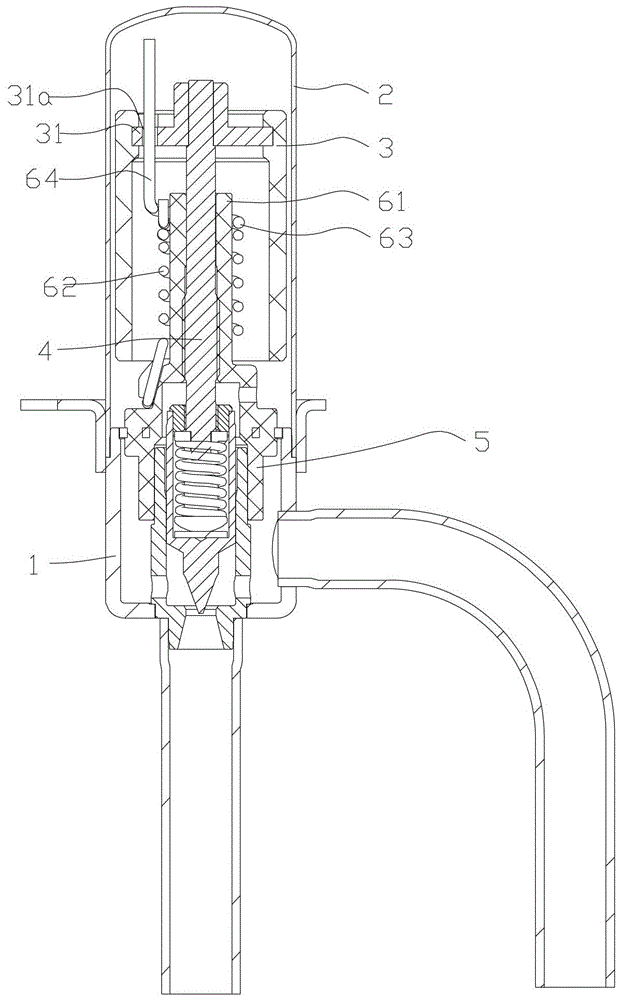
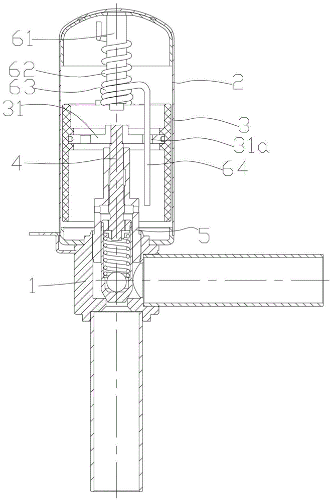
[0040] Please refer to figure 2 and image 3 , figure 2 It is a schematic structural diagram of the electronic expansion valve in the first embodiment of the present invention; image 3 It is a schematic structural diagram of the electronic expansion valve in the second embodiment of the present invention.

[0041] In the basic technical scheme of the presen...


PUM


Abstract

The invention discloses an electronic expansion valve, the stopping part of which includes a mandrel (61) fixed relative to a valve seat (1), a spring guide rail (62) sleeved on the outside of the mandrel (61), and the spring guide rail ( 62) A matching slip ring (63); one end of the slip ring (63) protrudes to form a stop rod (64), and a stop hole (31a) is opened on the top of the magnet (3), and the stop rod ( 64) pass through the stop hole (31a), and when the slip ring (63) is in the upper stop position and the lower stop position, the stop rod (64) is held in the stop hole (31a) . On the one hand, the structural design of the electronic expansion valve can reduce the number of parts, simplify the assembly process of the stop rod, and improve its working reliability; on the other hand, it can reduce the radial dimension of the magnet, thereby saving material costs and realizing Product miniaturization.

Description

technical field [0001] The invention relates to the technical field of fluid control components, in particular to an electronic expansion valve. Background technique [0002] In the technical field of refrigeration and heating, the electronic expansion valve is the refrigerant flow control part of the refrigeration and heating equipment. flow. [0003] In the prior art, the Chinese patent application publication number "CN102454819A" discloses an electronic expansion valve, specifically, please refer to figure 1 , figure 1 It is a structural schematic diagram of the electronic expansion valve in the prior art. [0004] Such as figure 1 As shown, the electronic expansion valve includes a valve seat 1' and a casing 2', and the casing 2' is fixedly supported on the valve seat 1', so that the relative position of the casing 2' and the valve seat 1' is fixed; the inside of the casing 2' A rotatable magnet 3' is provided, and the magnet 3' is fixedly connected with a screw 4'...

Claims


Application Information

Patent Timeline
Patent Type & Authority Patents(China)
IPC IPC(8): F25B41/06F16K31/06F25B41/31
CPCY02B30/70
Inventor 不公告发明人
Owner ZHEJIANG SANHUA INTELLIGENT CONTROLS CO LTD
Why Eureka
Try Eureka