
Laser line cross alignment control method for charging arm of electric vehicle

A technology of electric vehicle and control method, which is applied in the direction of electric vehicle charging technology, non-electric variable control, control/regulation system, etc., to achieve the effects of being less susceptible to interference, simple positioning control facilities, and high precision

Inactive Publication Date: 2014-02-12
CHONGQING UNIV OF ARTS & SCI
View PDF3 Cites 8 Cited by
  • Summary
  • Abstract
  • Description
  • Claims
  • Application Information

AI Technical Summary

Problems solved by technology

[0004] The present invention realizes the laser line cross alignment control method of the electric vehicle charging arm, uses the laser cross line to locate the object, and mainly solves the design and control of the object positioning facility based on the laser cross line

Method used


Image

  • Laser line cross alignment control method for charging arm of electric vehicle
  • Laser line cross alignment control method for charging arm of electric vehicle
  • Laser line cross alignment control method for charging arm of electric vehicle

Examples


Embodiment approach

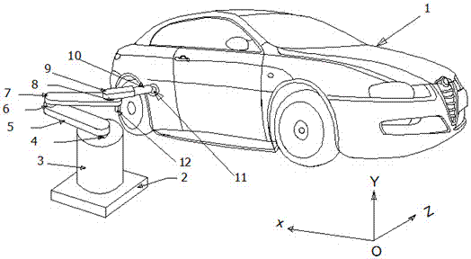
[0045] figure 1 The position structure diagram of electric vehicle and automatic charging arm provided for this embodiment includes electric vehicle 1, charging arm mounting base 2, charging arm vertical lifting assembly shell 3, first arm rotation shaft 4, first arm 5, The second support arm rotation shaft 6, the second support arm 7, the third support arm rotation shaft 8, the third support arm 9, the charging plug part 10, the charging socket part 11, the laser vertical line receiving assembly 12;

[0046] figure 2 A schematic diagram of the laser line emitting assembly provided for this embodiment, including the laser line emitting assembly 13;

[0047] image 3 The schematic diagram of the laser cross projected on the charging socket end provided for this embodiment includes the vertical laser line receiving component 14 and the horizontal laser line receiving component 15 of the third arm;

[0048] Figure 4 The structure diagram of the front end of the third arm o...


PUM


Abstract

The invention discloses a laser line cross alignment control method for a charging arm of an electric vehicle. According to the laser line cross alignment control method for the charging arm of the electric vehicle, a rear wheel limit slot, a rear wheel stop dog, the automatic charging arm, a first branch arm, a second branch arm, a third branch arm, a laser vertical line receiving assembly, a laser vertical line transmitting assembly, a third branch arm laser vertical line receiving assembly, a high-speed motor, a third branch arm rotary synchronous motor, a laser receiving assembly, a second branch arm rotary synchronous motor, a first branch arm rotary synchronous motor, a central processing unit, a signal monitoring circuit and an output drive circuit are included, an object is located through a laser cross line, a charging plug and a charging socket are located accurately before the electric vehicle is charged, and accurate butt joint between the charging plug and the charging socket is achieved. By the adoption of locating through the laser line, locating control facilities are simple, the locating precision is high, and interference is not prone to being caused.

Description

technical field [0001] The invention relates to a facility for automatic charging and automatic alignment of electric vehicles. Background technique [0002] The invention relates to a method for controlling the cross alignment of a laser line of a charging arm of an electric vehicle. At present, object positioning and operation are very complicated, such as the method and system for locating objects in Patent No. 201110062989, using UWB signals and wireless communication technology, the time difference between the respective receptions of the two positioning signals transmitted by the two antennas of the search device to locate the object , the system is complex, it is difficult to obtain high-precision object positioning, and it is susceptible to interference. Contents of the invention [0003] The problem to be solved by the invention [0004] The invention is to realize the control method of the laser line cross alignment of the electric vehicle charging arm, utilize...

Claims


Application Information

Patent Timeline
IPC IPC(8): G05D3/00
CPCY02T90/168Y04S30/12Y02T90/167
Inventor 不公告发明人
Owner CHONGQING UNIV OF ARTS & SCI
Learn More