System and method for conducting multi-network combination transmission and user equipment

A technology of user equipment and joint transmission, which is applied in the direction of network traffic/resource management, connection management, wireless communication, etc., and can solve problems such as high cost

Inactive Publication Date: 2014-02-12
ZTE CORP
View PDF8 Cites 62 Cited by
  • Summary
  • Abstract
  • Description
  • Claims
  • Application Information

AI Technical Summary

Problems solved by technology

[0011] The purpose of the present invention is to provide a system, user equipment and method for multi-network joint transmission, so as to overcome the defects of large cost of existing operators

Method used


Image

  • System and method for conducting multi-network combination transmission and user equipment
  • System and method for conducting multi-network combination transmission and user equipment
  • System and method for conducting multi-network combination transmission and user equipment

Examples


application example 1

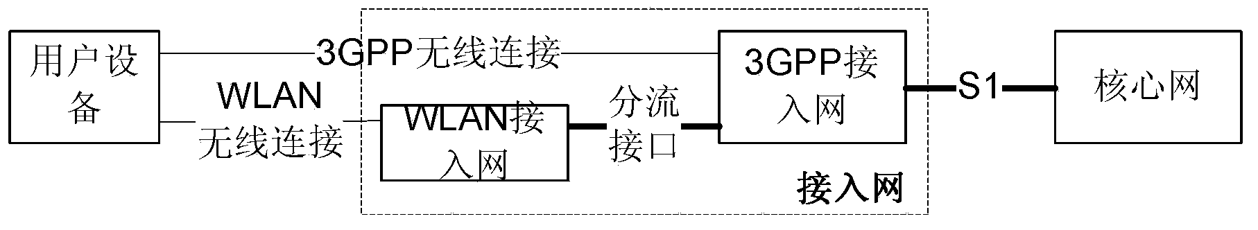
[0174] Application example 1: Take joint transmission of LTE and WLAN as an example.

[0175] Such as Figure 5 As shown, the eNB is connected to the LTE core network through the S1 interface; on the RAN (Radio Access Network, wireless access network) side, the eNB is also connected to the WLAN AP through the offload interface, wherein the data bottom layer on the offload interface is based on the Ethernet protocol for data exchange ; The UE performs data transmission with the eNB and the WLAN AP according to the Uu interface protocol and the WLAN air interface protocol respectively.

[0176] For the control plane signaling transmitted between the access network and the UE, the eNB still directly interacts with the UE through the Uu interface, and does not participate in data offloading.

[0177] For downlink user data, after receiving the user IP data on different bearers from the core network through the S1 port, the eNB distributes the user data on different bearers at the...

application example 2

[0184] Application example 2: take joint transmission of UMTS network and WLAN network as an example.

[0185] As shown in Figure 9(a), the RNC is connected to the core network through the Iu interface; on the RAN side, the RNC is also connected to the WLAN AP through the offload interface, where the data bottom layer on the offload interface is based on the Ethernet protocol for data exchange; The interface protocol and the WLAN air interface protocol perform data transfer with the RNC and the WLAN AP.

[0186] Optionally, the offload interface between the UMTS network and the WLAN AP may also be established between the NodeB and the AP, as shown in FIG. 9( b ).

[0187] For the control plane signaling transmitted between the access network and the UE, the RNC still interacts with the UE through the Uu interface, and does not participate in traffic distribution.

[0188] For the downlink user data, after the RNC receives the user IP data of different bearers from the core ne...


PUM


Abstract

A system, user equipment and method for implementing multi-network joint transmission. The system comprises: a core network and an access network; the access network comprises: a network element of a 3GPP access network and a network element of a WLAN access network; and the core network comprises: a network element of a 3GPP core network. The network element of the 3GPP access network is connected to the network element of the core network through a network interface, connected to the network element of the WLAN access network through a traffic distribution interface, and connected to a user equipment through a 3GPP wireless interface; and is used for combining received uplink user data; and used for implementing traffic distribution on downlink user data, to distribute a part of the downlink user data to the network element of the WLAN access network. The network element of the WLAN access network is connected to the user equipment through a WLAN wireless interface, and is used for transmitting uplink user data and downlink user data between the network element of the 3GPP access network and the user equipment. The present invention can reduce the network load and save the frequency band and the cost.

Description

technical field [0001] The present invention relates to a mobile communication system, in particular to a system, user equipment and method for multi-network joint transmission. Background technique [0002] With the continuous evolution of wireless communication technology and protocol standards, the mobile packet service has undergone tremendous development, and the data throughput capability of a single terminal has been continuously improved. Taking the Long Term Evolution (LTE for short) system as an example, it can support data transmission with a maximum downlink rate of 100 Mbps within a 20M bandwidth; in the subsequent enhanced LTE (LTE Advanced, LTE-A for short) system, data The transmission rate will be further improved, even reaching 1Gbps. [0003] The expansive growth of terminal data traffic has made the existing network resources gradually unable to cope, especially when the new generation of communication technologies (such as 3G (3rd-generation, third-gene...

Claims


Application Information

Patent Timeline
Patent Type & Authority Applications(China)
IPC IPC(8): H04W28/06H04W28/10
CPCH04W76/025H04W28/08H04W92/20H04W88/06H04W76/16H04W28/0846H04W36/22
Inventor 王昕和峰
Owner ZTE CORP
Why Eureka
Try Eureka