Fine particle aggregating device under aggregating agent and jet effects

A technology of particle agglomeration and agglomeration agent, applied in the field of flue gas dust removal, it can solve problems such as changing particle surface and increasing effective collision between particles, and achieves the effect of solving bottleneck restrictions, wide operating area and simple equipment

Inactive Publication Date: 2014-02-19
QINGDAO UNIV
View PDF6 Cites 8 Cited by
  • Summary
  • Abstract
  • Description
  • Claims
  • Application Information

AI Technical Summary

Problems solved by technology

The agglomeration device uses the jet to generate turbulent disturbance to the flow field to increase the effective collision between particles; the agglomerating agent is used to change the adhesion of the particle surface, and the coupling of the two can overcome the shortcomings of a single agglomeration method

Method used


Image

  • Fine particle aggregating device under aggregating agent and jet effects

Examples


Embodiment Construction

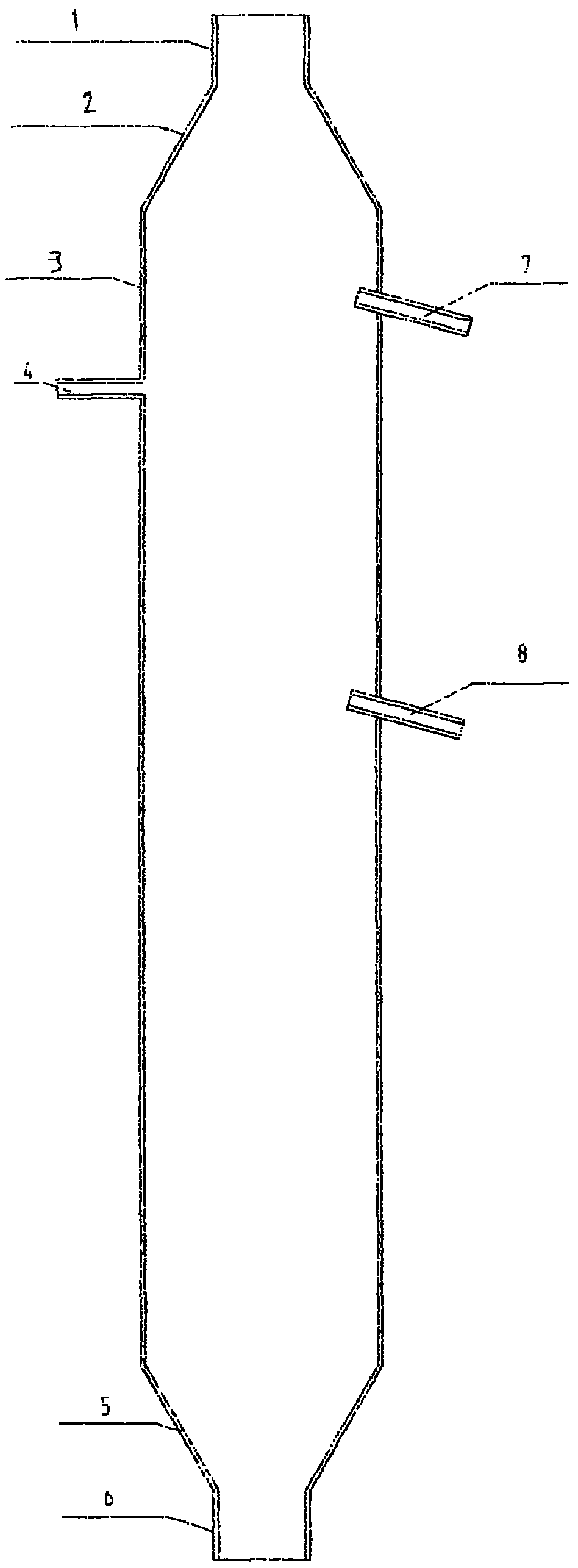
[0011] combined with figure 1 The agglomeration device of the present invention is described. The agglomeration device includes a dusty gas inlet 1, an enlargement section 2, a particle agglomeration chamber 3, a contraction section 5, a narrowing outlet 6, a primary jet tube 7, a secondary jet tube 8 and an agglomerating agent spray port 4 . The particle agglomeration chamber 3 is a three-dimensional vertical equipment with a section of 400×400mm and a height of 2000mm. The dusty gas inlet 1 and the narrowing outlet 5 are circular connection ports with a diameter of 150mm. The enlargement section 2 is a smooth enlargement inlet. In order to achieve the best effect, the included angle of the inlet is 20-30°; the shrinkage section 5 is also a smooth transition structure to reduce the impact of the shrinkage structure on the fragmentation and disturbance of particle aggregates. The primary jet tube 7 is installed on the rear side of the amplification section 3.5d 0 , fixed on...


PUM


Abstract

The invention relates to an aggregation removing device for fine particles under aggregating agent and jet effects. The device mainly structurally comprises a particle aggregating room, a primary jet pipe, a secondary jet pipe and an aggregating agent spraying port. The particle aggregating room is three-dimensional vertical equipment with a square section. The primary jet pipe is mounted on the side surface of the aggregating room and the back section of an amplifying section; the secondary jet pipe and the primary jet pipe are mounted at the downstream of the same side of the aggregating room. The aggregating agent spraying port is vertically mounted on the side surface of the aggregating room opposite to the jet pipe; the mounting position is arranged between the primary jet pipe and the secondary jet pipe. In the aggregating room, the particles are modified through the aggregating agent, and the collision among the particles is reinforced through jetting, so that the absorbable particles less than 10 microns can be fully aggregated and removed.

Description

technical field [0001] The invention belongs to the field of flue gas dust removal, and in particular relates to a device for agglomerating and removing fine particles under the coupling action of an agglomerating agent and jet flow. Background technique [0002] Energy and the environment are the basic conditions for the survival and development of human beings in the 21st century. While energy promotes economic development, it also brings environmental pollution. Fine particulate matter produced by fossil fuel combustion has become a prominent pollutant in the urban atmosphere, which has attracted great attention from all over the world. In the air pollution of cities in my country, particulate matter pollution is the primary source of pollution, especially the aerodynamic diameter less than 2.5 μm (PM 2.5 ) of ultrafine particles. Fine particles are easily inhaled by the nose and mouth, and are closely related to human health. The harm of particulate matter to the huma...

Claims


Application Information

Patent Timeline
Patent Type & Authority Applications(China)
IPC IPC(8): B01D51/02B03C3/013
Inventor 孙德帅张晓东方龙张中一
Owner QINGDAO UNIV
Why Eureka
Try Eureka