
Method for fixedly connecting embedded bars in assembly-type structure and cast-in-place structure

A pre-embedded reinforcement and prefabricated technology, applied in structural elements, building components, building structures, etc., can solve the large butt joint misalignment between the sleeve and the pre-embedded reinforcement, and the inaccurate docking and positioning of the prefabricated shear wall and the lower wall Inaccurate pre-embedded steel bars and other issues to achieve the effect of ensuring strength, preventing adverse effects, and conveniently obtaining materials

Active Publication Date: 2014-02-19
SHANGHAI CONSTR NO 5 GRP CO LTD +1
View PDF6 Cites 13 Cited by
  • Summary
  • Abstract
  • Description
  • Claims
  • Application Information

AI Technical Summary

Problems solved by technology

[0004] For the existing prefabricated shear wall connection method, the steel sleeve plate is used to locate the embedded steel bar inaccurately, which makes the sleeve and the embedded steel bar butt joint misalignment, which leads to the problem that the prefabricated shear wall and the lower wall cannot be accurately docked

Method used


Image

  • Method for fixedly connecting embedded bars in assembly-type structure and cast-in-place structure
  • Method for fixedly connecting embedded bars in assembly-type structure and cast-in-place structure
  • Method for fixedly connecting embedded bars in assembly-type structure and cast-in-place structure

Examples


Embodiment Construction

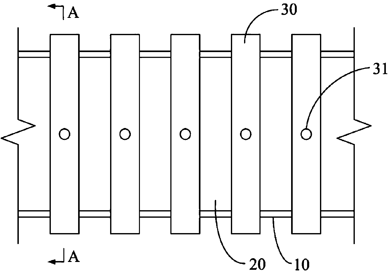
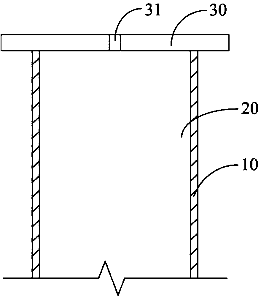
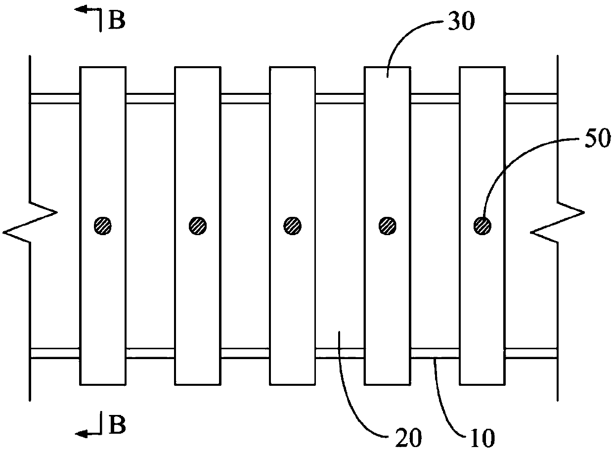
[0031] The fixed connection method of the prefabricated structure and the pre-embedded steel bar in the cast-in-place structure proposed by the present invention will be further described in detail below in conjunction with the accompanying drawings and specific embodiments. Advantages and features of the present invention will be apparent from the following description and claims. It should be noted that all the drawings are in a very simplified form and use imprecise scales, and are only used to facilitate and clearly assist the purpose of illustrating the embodiments of the present invention. For the convenience of description, the "up" and "down" described below are consistent with the directions of up and down in the drawings, but this should not be a limitation of the technical solution of the present invention.

[0032] combine Figure 1 to Figure 8 Illustrate the fixed connection method of the prefabricated steel bar in the prefabricated structure of the present inven...


PUM


Abstract

The invention provides a method for fixedly connecting embedded bars in an assembly-type structure and a cast-in-place concrete structure and relates to the technical field of building structure connection. The problems that according to an existing connecting method of a prefabricated shear wall, steel bars are not positioned accurately by a steel bushing plate, so that butt joint mismatch of sleeves and the steel bars is large, and therefore the phenomenon that accurate butt joint of the prefabricated shear wall and a lower-layer wall body can not be achieved is caused are solved. The method comprises the steps that firstly, a wooden bushing board provided with a plurality of base holes is provided and the base holes can correspond to the positions of bushings in an assembly-type reinforced concrete structure; secondly, template supporting is conducted on the position where the concrete structure needs to be cast in place so that a chamber can be formed, the wooden bushing board is fixed to the top end of the chamber, and the embedded bars penetrate through the wooden bushing board and are implanted in the chamber so that positioning can be achieved; thirdly, concrete is poured to the chamber, and after the concrete is hardened, the wooden bushing board is detached, so that the cast-in-place concrete structure is manufactured; fourthly, the assembly-type reinforced concrete structure and the cast-in-place concrete structure are in butt joint and are fixed; fifthly, a gap of the connection portion of the wall body is plugged so that assembly construction can be accomplished.

Description

technical field [0001] The invention relates to the technical field of connection of building structures, in particular to a fixed connection method between an assembled reinforced concrete structure and a pre-embedded steel bar in a cast-in-situ concrete structure. Background technique [0002] Prefabricated reinforced concrete structure (referred to as prefabricated structure) is a concrete structure that is assembled or connected with prefabricated components as the main force-bearing components. It can reduce wet operations such as pouring concrete on site, improve the degree of assembly, and shorten the construction period. In the process of high-rise building construction, in order to resist external forces such as earthquakes, it is necessary to connect adjacent prefabricated reinforced concrete structures into a whole, so as to facilitate the transmission of vertical reaction force and horizontal shear force, and ensure the safety of the building. [0003] The appli...

Claims


Application Information

Patent Timeline
Patent Type & Authority Applications(China)
IPC IPC(8): E04B2/00E04B2/84E04C5/16E04G21/00
Inventor 赵德峰方怡陈建华王甘球李少龙吴聪聪王水良
Owner SHANGHAI CONSTR NO 5 GRP CO LTD
Learn More