
Test Structure and Test Method for Dielectric Breakdown Reliability Analysis in Integrated Circuits

A dielectric breakdown and integrated circuit technology, applied in the direction of circuits, testing dielectric strength, electrical components, etc., can solve the problem that the F3 position is easy to be broken down, the reliability analysis accuracy of the interconnection line cannot be guaranteed, and the dielectric cannot be completely tested The place where the withstand voltage capability needs to be evaluated, etc., to reduce the possibility of burnout, ensure smooth progress, and ensure the effect of accuracy

Active Publication Date: 2016-07-06
SEMICON MFG INT (SHANGHAI) CORP
View PDF4 Cites 0 Cited by
  • Summary
  • Abstract
  • Description
  • Claims
  • Application Information

AI Technical Summary

Problems solved by technology

However, in an actual integrated circuit, the first metal line structure 112 and the upper layer metal line 132 are connected through a via structure 141, Figure 5 It is a cross-sectional view of the interconnection structure in the actual circuit, in Figure 5 In the actual circuit, the place with the worst dielectric withstand voltage capability between the interconnection lines includes the F1 position and the F2 position, Figure 5 The distance between the via structure 141 at the F3 position and the underlying metal line structure 102 is relatively close, even smaller than the widths of F1 and F2, and the F3 position is easily broken down when a voltage is applied, so the existing test structure has been It cannot reflect the place where the dielectric withstand voltage capability of the interconnection lines is the worst in the actual circuit, and cannot fully test the places where the dielectric withstand voltage capability needs to be evaluated, so that the accuracy of the reliability analysis of the interconnection lines cannot be guaranteed.

Method used


Image

  • Test Structure and Test Method for Dielectric Breakdown Reliability Analysis in Integrated Circuits
  • Test Structure and Test Method for Dielectric Breakdown Reliability Analysis in Integrated Circuits
  • Test Structure and Test Method for Dielectric Breakdown Reliability Analysis in Integrated Circuits

Examples


no. 1 example

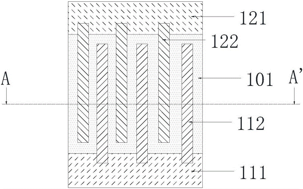
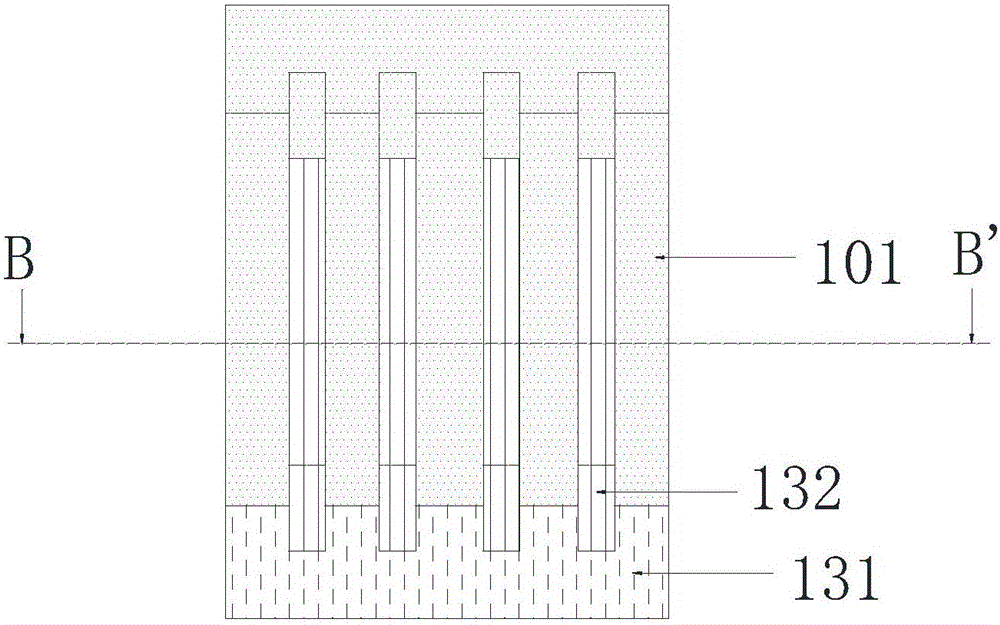
[0055] In the first embodiment, the lower metal wire structure and the upper metal wire structure include several linear metal wires arranged in parallel. Please refer to the following Figure 6-Figure 8 ,in, Figure 6 It is a top view of the test structure of the dielectric breakdown reliability analysis in the integrated circuit in an embodiment of the present invention, Figure 7 It is a right view of the test structure for the reliability analysis of the dielectric breakdown in the integrated circuit in an embodiment of the present invention, Figure 8 for Figure 6 Sectional view along cutting line C-C'. In the figures, the same reference numerals represent equivalent Figure 1-Figure 5 label in .

[0056] Such as Figure 6 As shown, the underlying metal wire structure 102 includes a first metal wire structure 112 and a second metal wire structure 122 arranged at intervals. In a preferred embodiment, the first metal wire structure 112 and the second metal wire stru...

no. 2 example

[0069] Please refer to the following Figure 11 , Figure 11 It is a top view of a test structure for dielectric breakdown reliability analysis in an integrated circuit in another embodiment of the present invention. In the figure, the same reference numerals represent the same as Figure 1-Figure 7 label in . The second embodiment is based on the first embodiment, the difference is that the first metal wire structure 112 and the second metal wire structure 122 are comb-shaped, and the first metal wire structure 112 includes more than one metal wire and one metal connection wire 201, the second metal wire structure 122 includes more than one metal wire and one metal connection wire 202, and each of the more than one metal wires included in the first metal wire structure 112 is connected to the metal connection wire 201 included in the first metal wire structure 112 through its one end. Each of the one or more metal wires included in the second metal wire structure 122 is conne...


PUM


Abstract

The invention discloses a test structure for reliability analysis of dielectric breakdown in an integrated circuit. The test structure comprises: a lower metal wire structure, including a first metal wire structure and a second metal wire structure arranged at intervals; an upper metal wire structure ; Via structure and dielectric. The present invention also discloses a test method for the test structure, including: providing a substrate, forming an actual structure to be tested on the substrate according to the test structure; measuring the metal line structure of the lower layer in the actual structure to be tested The dielectric breakdown reliability between adjacent metal lines, the dielectric breakdown reliability between the upper metal line structure and the lower metal line structure in the actual structure to be tested, the relationship between the through hole and the adjacent metal line in the actual structure to be tested Dielectric breakdown reliability between second metal line structures. The test structure of the invention can accurately evaluate the place where the withstand voltage capability of the dielectric in the actual circuit needs to be evaluated, thereby ensuring the accuracy of the reliability analysis of the interconnection line.

Description

technical field [0001] The invention relates to the reliability (Reliability) field in the semiconductor manufacturing industry, in particular to a test structure and a test method for dielectric breakdown reliability analysis in integrated circuits. Background technique [0002] Reliability issues in Very Large Scale Integration (VLSI) are affected by device and interconnect technologies. As the feature size (CriticalDimension) shrinks, the gate delay of the device is reduced, and the interconnection performance of the circuit is also reduced. This is because the reduction of the feature size will lead to a reduction in the cross-sectional area and line spacing of the interconnection lines, and the parasitic effects caused by resistance, capacitance, and inductance will seriously affect the performance of the circuit. Therefore, the reliability of interconnection has become an important factor restricting the reliability of the system. In order to reduce the resistance-ca...

Claims


Application Information

Patent Timeline
Patent Type & Authority Patents(China)
IPC IPC(8): H01L23/544G01R31/12
Inventor 王笃林
Owner SEMICON MFG INT (SHANGHAI) CORP
Learn More