
Low-hybrid-wave antenna phase compensation method

A phase compensation, low clutter technology, applied in the field of magnetic confinement fusion research, to achieve the effect of eliminating 180-degree phase difference

Inactive Publication Date: 2014-02-19
INST OF PLASMA PHYSICS CHINESE ACAD OF SCI
View PDF4 Cites 12 Cited by
  • Summary
  • Abstract
  • Description
  • Claims
  • Application Information

AI Technical Summary

Problems solved by technology

For the most commonly used multi-junction waveguide antenna (MJ antenna) and active-passive interleaved multi-junction waveguide antenna (PAM antenna), the same wave source often uses a mode converter as a power splitter, and each main The circular power division structure of the waveguide and the arrangement of the phase shifter are the same. In the prior art, these two phase differences cannot be eliminated by controlling the low-power phase shifter at the front stage.

Method used


Image

  • Low-hybrid-wave antenna phase compensation method
  • Low-hybrid-wave antenna phase compensation method
  • Low-hybrid-wave antenna phase compensation method

Examples


Embodiment Construction

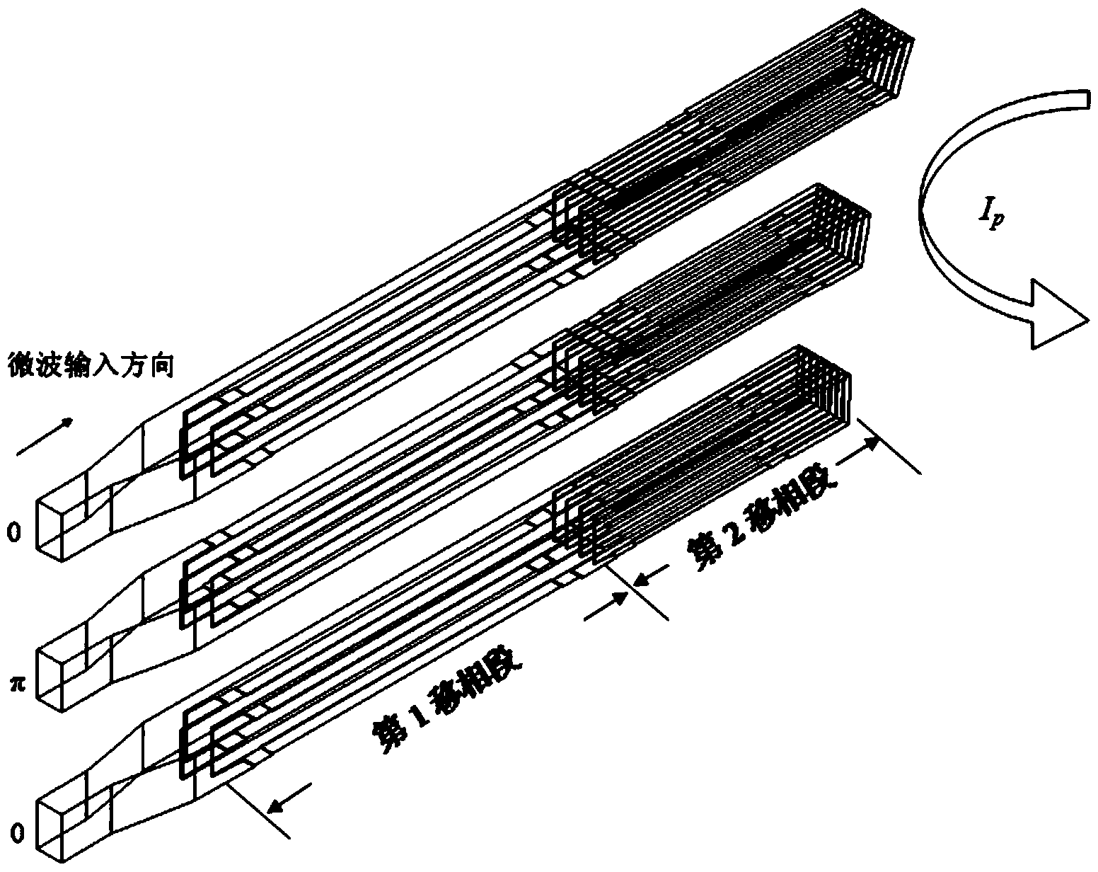
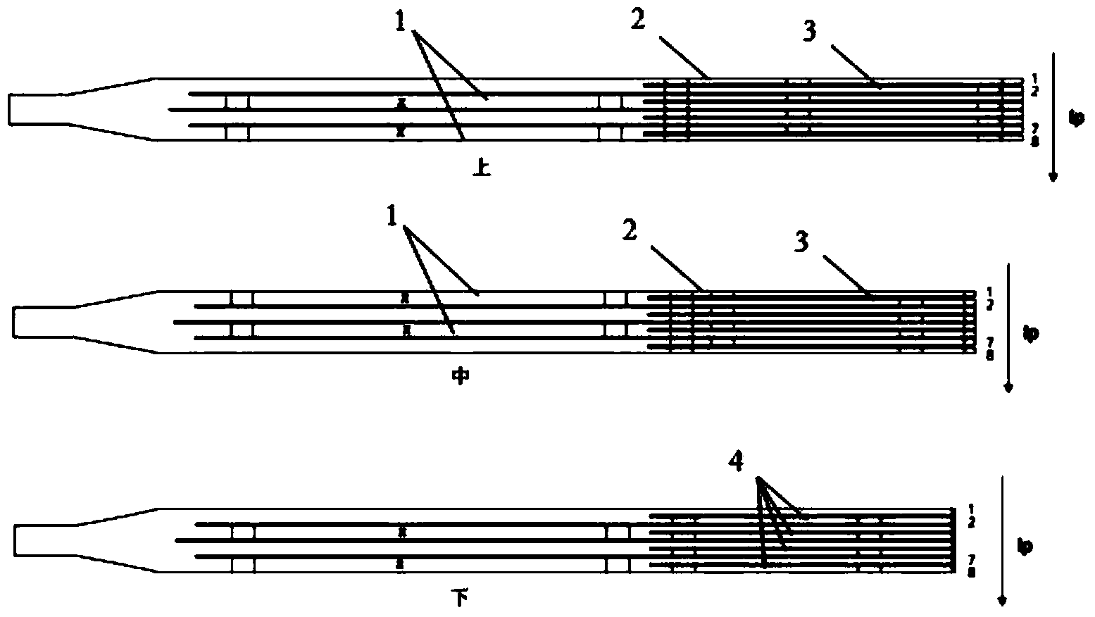
[0021] The structural diagram of the antenna unit of the present invention is as follows figure 1 As shown, the antenna unit consists of three rows of waveguides fed by the same klystron. This embodiment is a 4.6 GHz low-clutter multi-junction waveguide antenna of the EAST tokamak device. The actual low-clutter waveguide array antenna is composed of 24 similar antenna elements arranged in 4 rows and 6 columns. The microwave energy of each klystron is divided into three waveguide outputs in the pole direction through the TE10-TE30 mode converter, and then connected to figure 1 Three-row waveguide for medium antenna unit. The present invention adopts the following method to eliminate the fixed phase difference in the multi-junction waveguide antenna (MJ antenna):

[0022] 1. The three-row main waveguide of the antenna unit, such as figure 1 As shown, it includes a section of linear transition waveguide whose narrow side becomes wider gradually, and divides the main waveguide ...


PUM


Abstract

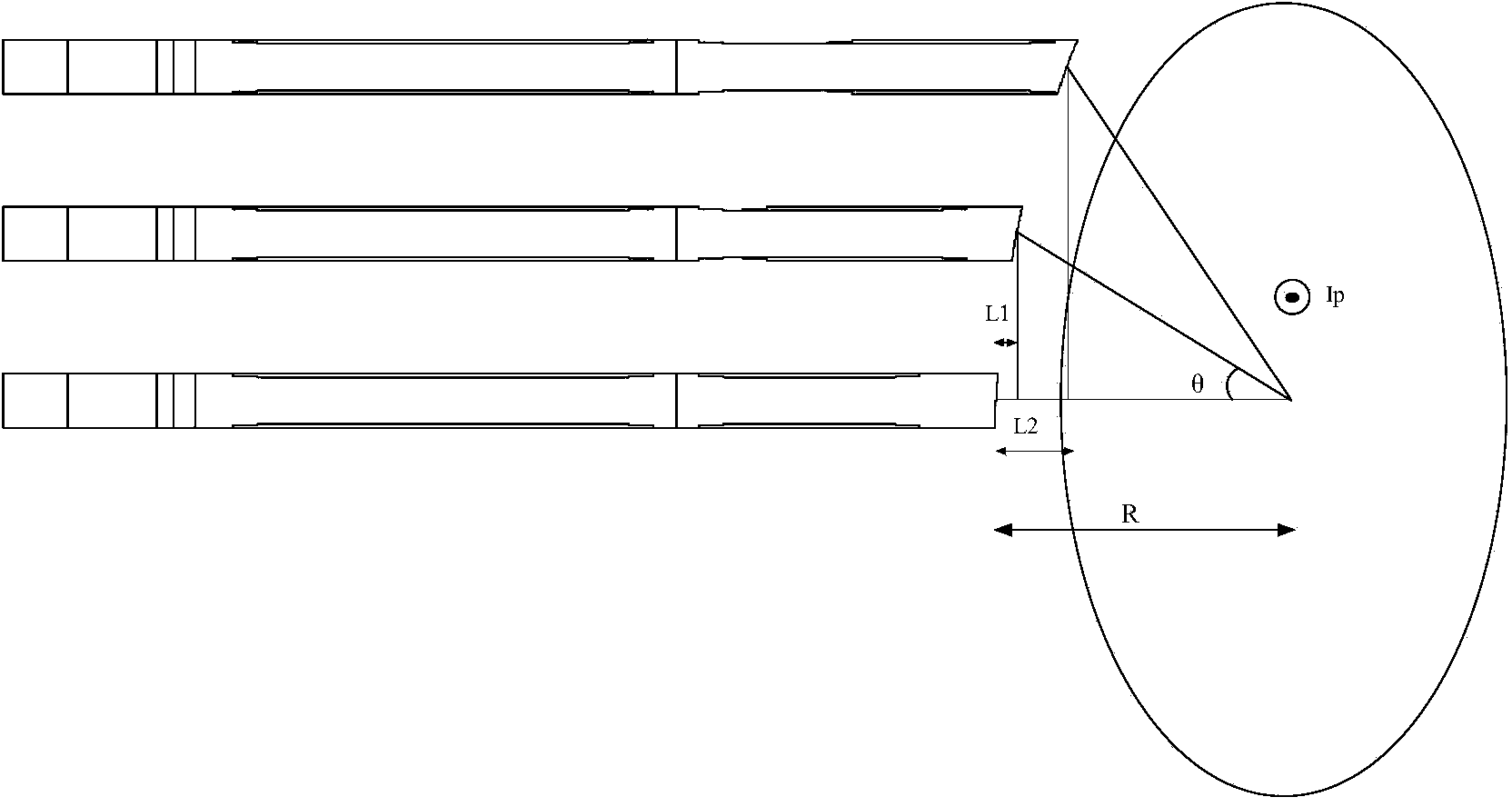
The invention discloses a low-hybrid-wave antenna phase compensation method. Three lines of main waveguide of an antenna unit respectively comprises a section of linear transitional waveguide with the gradually-widened narrow edge. A main waveguide is divided into N / 2 sections of branch waveguide through E face branch waveguide of a first phase shift section, then, the main waveguide is divided into N sections of branch waveguide in a second phase shift section, and N is an even number. Phase shifters are arranged through two methods respectively, and the 180-degree phase difference brought by an output port in the middle line of a mode converter and the phase difference caused by the waveguide length difference which is caused by an antenna port arc notch can be eliminated. The low-hybrid-wave antenna phase compensation method can be applied to the design of a Tokamak low-hybrid-wave multi-junction waveguide antenna and an active and passive staggered multi-junction waveguide PAM antenna of a nuclear fusion experimental device and can be used for eliminating various phase differences of the antennas and improving the coupling performance and current drive efficiency of the antennas and plasmas.

Description

technical field [0001] The invention relates to the field of magnetic confinement fusion research, in particular to a phase compensation method for a low clutter antenna of a tokamak device. Background technique [0002] The tokamak device is an experimental device for magnetic confinement fusion research. Low clutter is one of the important means of current driving and auxiliary heating on the tokamak. The principle is to use high-power microwave energy to heat the plasma. The method adopted in the low clutter current drive technology is to send microwave energy to the plasma of the tokamak through the waveguide array antenna. The waveguide array antenna is composed of a rectangular array composed of a plurality of rectangular sub-waveguides arranged in rows and columns, and each rectangular sub-waveguide is a radiation unit. The power spectrum emitted by the low-clutter antenna array is related to wave accessibility and power deposition. It needs to meet certain conditio...

Claims


Application Information

Patent Timeline
IPC IPC(8): H01Q3/30
Inventor 贾华刘亮程敏赵连敏刘甫坤单家方
Owner INST OF PLASMA PHYSICS CHINESE ACAD OF SCI
Learn More