Design method of middle-long line transmission filter of motor drag system

A technology of drag system and design method, which is applied in the direction of controlling electromechanical brakes, control systems, and control generators, etc., and can solve the problems of lack of practical guidance and no involvement of LCR filters, etc.

Inactive Publication Date: 2014-02-19
朱淼 +1
View PDF7 Cites 10 Cited by
  • Summary
  • Abstract
  • Description
  • Claims
  • Application Information

AI Technical Summary

Problems solved by technology

However, this patent does not involve the design process of the s

Method used


Image

  • Design method of middle-long line transmission filter of motor drag system
  • Design method of middle-long line transmission filter of motor drag system
  • Design method of middle-long line transmission filter of motor drag system

Examples


Embodiment Construction

[0063] The present invention will be described in detail below in conjunction with specific embodiments. The following examples will help those skilled in the art to further understand the present invention, but do not limit the present invention in any form. It should be noted that those skilled in the art can make several modifications and improvements without departing from the concept of the present invention. These all belong to the protection scope of the present invention.

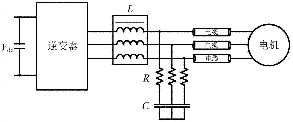
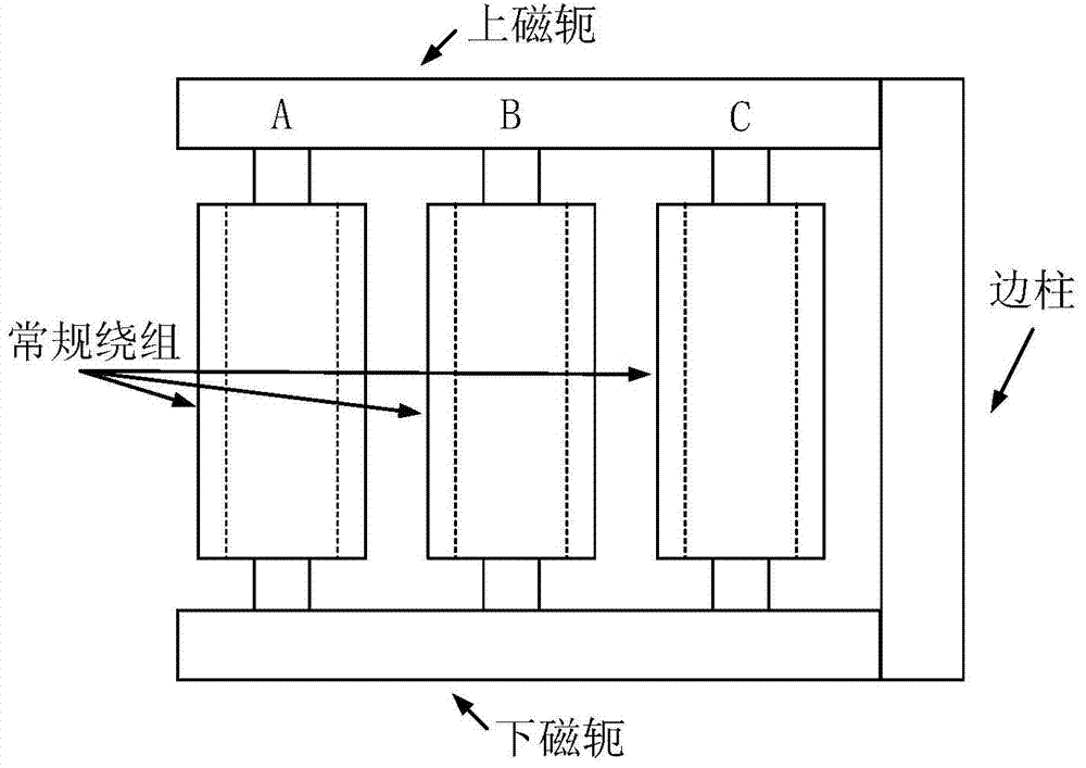
[0064] This embodiment provides a design method for a long-line propagation filter in a motor drive system, such as figure 1 As shown, the method adopts the LCR type second-order filter on the inverter side to realize overvoltage limitation and voltage rise rate limitation. like figure 1 As shown, the reactor in the LCR type second-order filter adopts a four-column three-phase reactor with a common mode path. Compared with the conventional filter, this type of reactor has the following structure:...


PUM


Abstract

The invention provides a design method of a middle-long line transmission filter of a motor drag system. The method involves that an LCR-type filter structure is adopted on the side of an inverter to lower the amplitude of voltages arriving at the motor end and the corresponding dv/dt, so that the requirement of motor insulation is met. The method specifically includes the following four steps of determining the size of an output inductor L, determining the size of a filter resistor R, determining the size of a filter capacitor C and conducting parameter modification. By means of the design method, a unified theory is provided for the design method of the filter on the side of the inverter according to the working condition that long line drive is adopted in motor drag control, and the design of the dv/dt filter can be guided more thoroughly; by the adoption of the LCR-type filter, the advantages of being simple in structure, low in cost, small in size, obvious in overvoltage restraining effect and the like.

Description

technical field [0001] The invention relates to the field of power electronics, in particular to a design method of a long-line propagation filter in a motor drive system, which is suitable for applications such as a motor drive control system. Background technique [0002] Modern motor control generally adopts flux-oriented vector control technology, based on the topology of a three-phase voltage source PWM inverter (VSI) to achieve high-performance motor drag control. However, in many cases, the inverter output needs to drive the motor through a long cable. Due to the serious mismatch between the cable impedance and the motor impedance and the cable impedance and the output impedance of the inverter, the voltage wave will occur during the propagation process. Reflection, so that the voltage wave will produce overvoltage when it reaches the motor end, and in severe cases, it will appear 2 times V dc Even higher overvoltage phenomenon, which will have a serious impact on th...

Claims


Application Information

Patent Timeline
IPC IPC(8): H02P27/08H02P21/00H02M1/00
Inventor 朱淼王鹏
Owner 朱淼
Why Eureka
Try Eureka