LID (low impact development) type rainwater ditch and design and calculation method for same

A rainwater ditch, design and calculation technology, applied in the field of LID rainwater ditch and its design calculation, can solve the problems of single function, difficult to drain smoothly, aggravate the surface source of rainwater, etc. The effect of water environment

Active Publication Date: 2014-02-26
XIAMEN UNIV OF TECH
View PDF11 Cites 16 Cited by
  • Summary
  • Abstract
  • Description
  • Claims
  • Application Information

AI Technical Summary

Problems solved by technology

[0002] The traditional hardened stormwater ditches are only built to quickly discharge the surrounding rainwater runoff into the receiving water body, and their single function is only "drainage"
This single function not only gives full play to the advantages of drainage, but also brings the following problems: it intensifies the flood pressure of the receiving water body in the rainy season and the occurrence of flood disasters, and it is difficult for rainwater to infiltrate and recharge groundwater through the ditch bed, which makes the river prone to dry up in the dry season , in addition to exacerbating the problem of non-point source pollution of rainwater
This patent builds ditches into wetlands to reduce rainwater non-point source pollutants. Its main disadvantages are: 1) It is not suitable for drainage ditches with large drainage and fast drainage speed. It is easy to be washed away, and secondly, the water flow shuttles among the wetland plants, which suffers from great resistance and is difficult to drain...

Method used


Image

  • LID (low impact development) type rainwater ditch and design and calculation method for same
  • LID (low impact development) type rainwater ditch and design and calculation method for same
  • LID (low impact development) type rainwater ditch and design and calculation method for same

Examples


Embodiment Construction

[0060] The present invention will be further described in detail below in conjunction with the accompanying drawings and specific embodiments.

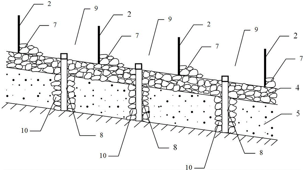
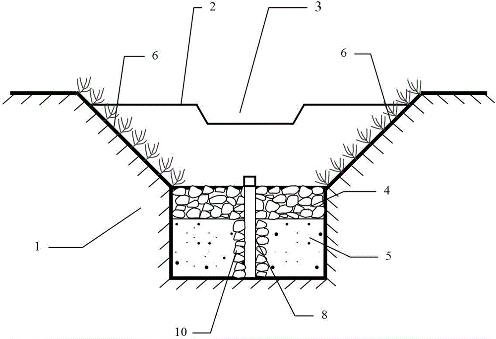
[0061] What the present invention discloses is a kind of LID type rainwater ditch, as figure 1 and figure 2 Shown is a preferred embodiment of the present invention. The rainwater ditch includes a ditch body 1, a storage dam 2, an overflow outlet 3, a rough stone layer 4, a sandy soil layer 5, and an ecological slope 6, and the dam foot protection stone 7 and a rainwater outlet can be further set. Permeation well or permeation tube8. in:

[0062] A layer of sand layer 5 is first laid on the bed surface of the ditch body 1, and a layer of coarse stone layer 4 is laid on the top of the sand layer 5, and the described storage dam 2 is continuous at intervals along the longitudinal direction of the ditch body 1. Set so that the ditch forms a series of continuously distributed reservoirs 9 along the way. Each storage dam 2 is provid...


PUM


Abstract

The invention discloses an LID (low impact development) type rainwater ditch and a design and calculation method for the same, and is applicable to various rainwater drainage ditches such as drainage ditches, farmland drainage ditches and floodwater drainage ditches on two sides of a slope and two sides of a road. The rainwater ditch comprises a ditch, storage dams, overflow ports, a rubble layer, a sandy soil layer, ecological slopes and the like. The sandy soil layer is laid on a bed of the ditch, the rubble layer is laid on the upper side of the sandy soil layer, and the storage dams are longitudinally continuously arranged along the ditch and are separated from one another by a certain distance, so that a series of reservoirs which are continuously distributed are formed along the ditch. The design and calculation method includes designing and calculating layout spacing of the water storage dams and the sizes of the overflow ports. The LID type rainwater ditch and the design and calculation method have the advantages that the LID type rainwater ditch has multiple functions of 'drainage, water storage, infiltration and decontamination', and is incomparable to a hard rainwater ditch only with a drainage function; the LID type rainwater ditch is high in water storage capacity and drainage speed which are deficient in a wetland bed type rainwater ditch; the rainfall flood runoff volume can be obviously reduced, the groundwater recharge can be improved, non-point surface pollutants of rainwater can be reduced, and environments can be beautified.

Description

technical field [0001] The invention belongs to the technical field of water conservancy engineering and municipal engineering, and specifically relates to a LID type rainwater ditch and a design calculation method thereof. Background technique [0002] The purpose of traditional hardened rainwater ditches is only to quickly discharge the surrounding rainwater runoff into the receiving water body, and its single function is only "drainage". This single function not only gives full play to the advantages of drainage, but also brings the following problems: it intensifies the flood pressure of the receiving water body in the rainy season and the occurrence of flood disasters, and it is difficult for rainwater to infiltrate and recharge groundwater through the ditch bed, which makes the river prone to dry up in the dry season , in addition to exacerbating the problem of non-point source pollution of rainwater. In particular, most of the rivers used as sources of drinking water...

Claims


Application Information

Patent Timeline
IPC IPC(8): E02B5/00E03F5/00
Inventor 朱木兰
Owner XIAMEN UNIV OF TECH
Why Eureka
Try Eureka