Connection device and connection method for preventing steel structure column foot from being tensioned

A connecting device and steel structure technology, which is applied in basic structure engineering, building construction, construction, etc., can solve the problems of weak safety redundancy of column feet, increase of column foot area, and hidden safety hazards in steel structure systems, etc., to achieve The effect of improving safety redundancy, improving connection stiffness, and eliminating potential safety hazards

Inactive Publication Date: 2014-02-26
江苏祥珑石业有限公司
View PDF4 Cites 5 Cited by
  • Summary
  • Abstract
  • Description
  • Claims
  • Application Information

AI Technical Summary

Problems solved by technology

Relying on a limited number of anchor bolts to resist the tensile force will cause at least two problems: 1) The diameter of the anchor bolts is usually very thick, which is very difficult to resist the tensile force, and even the anchor bolts need to be densely distributed, so the column foot has to be enlarged area, consumes a lot of materials, and what is more potentially threatening is that any failure of any anchor bolt will cause fatal damage, that is, the safety redundancy of the column foot becomes the weak link of the steel structure system
2) Since the anchor bolts of the foundation are stretched and deformed, the bottom plate of the column foot has a tendency to break away from the foundation, so that the steel column and the foundation cannot actually form a fixed connection, but a spring connection
However, during the design, the internal force and deformation analysis was carried out according to the fixed connection, which caused potential safety hazards in the entire steel structure system.
[0004] The weakening of the connection stiffness caused by the tension of the bolts mentioned above not only exists at the foot of the column, but also exists in the upper beam-column connection, such as image 3 shown

Method used


Image

  • Connection device and connection method for preventing steel structure column foot from being tensioned
  • Connection device and connection method for preventing steel structure column foot from being tensioned
  • Connection device and connection method for preventing steel structure column foot from being tensioned

Examples


Embodiment 1

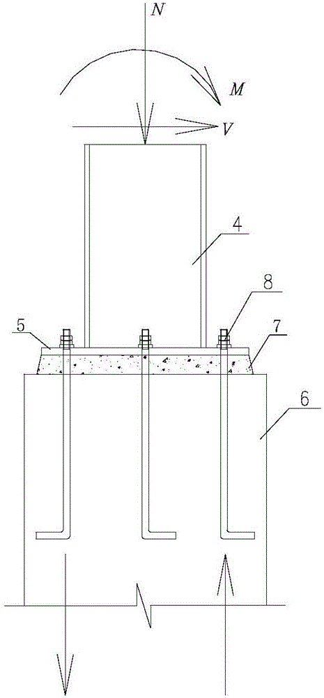
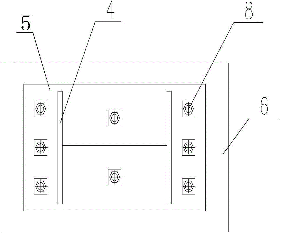
[0040] The steel structure column foot of the present invention is a tension-free connection member, such as Figure 4 , 5 As shown in, 6, it is composed of prestressed tie rod pair 1, combined gusset plate 2 and embedded casing 3. The prestressed tie rod pair 1 is formed by connecting the upper and lower steel tie rods 11 with threads on the two ends to be integrated by the positive and negative buckle sleeves 12; the lower steel tie rod 11 of the prestressed tie rod pair 1 passes through and is embedded in the concrete foundation. 6 The embedded casing 3 on the tension side is connected with the nut 13; the upper steel tie rod 11 of the prestressed tie rod pair 1 passes through the hole in the pre-welded composite gusset plate 2 on the tension side of the steel column and the nut 13 Connection; the upper and lower steel tie rods 11 of the prestressed tie rod pair 1 apply prestress to the steel tie rod 11 by rotating the positive and negative buckle sleeve 12.

[0041] Wherein, ...

Embodiment 2

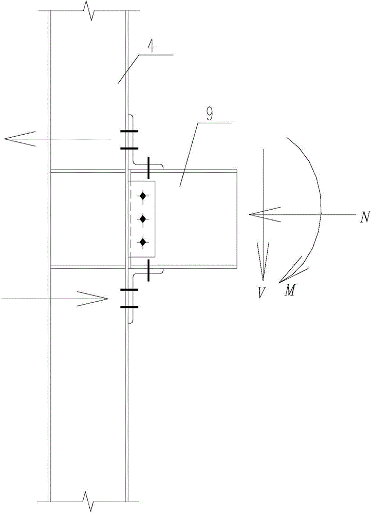
[0054] The tension-free connection member and method of the steel structure column foot of the present invention are applied to beam-column connection.

[0055] Such as Picture 9 , 10 As shown, the tension-free connection member of the column foot of the steel structure of the present invention is applied to the connection of beams and columns, and is composed of a prestressed tie rod pair 1 and a combined gusset plate 2.

[0056] Such as Image 6 As shown, the pre-stressed tie rod pair 1 is formed by connecting two sections of steel tie rods 11 with threads at both ends through positive and negative buckle sleeves 12, and the steel tie rod 11 is made of high-strength round steel.

[0057] The combined gusset plate 2 is composed of three plates, of which the right-angled sides of the two right-angled triangle plates and the rectangular plate are welded together in a "∏" shape.

[0058] The combined gusset plate 2 is pre-welded on the outside of the tension flange of the steel beam 9. ...


PUM


Abstract

The invention discloses a connection device and a connection method for preventing a steel structure column foot from being tensioned. The connection device comprises a prestressing pull bar pair, a combined node plate and an embedded casing. The prestressing pull bar pair formed by integrally connecting an upper section of a steel pull bar with a lower section of the steel pull bar through a forward and reverse buckle casing, and two ends of the steel pull bar are provided with threads; the lower section of the steel pull bar of the prestressing pull bar pair penetrates the embedded casing embedded in a tension side of a concrete foundation in advance to be connected with a nut; the upper section of the steel pull bar of the prestressing pull bar pair penetrates a hole formed in the combined node plate welded to the tension side of a steel column in advance to be connected with the nut; the upper and lower sections of the steel pull bar exert prestress upon the steel pull bar through the forward and reverse buckle casing. Therefore, the steel column foot can be prevented from being tensioned, using amount of sill anchors can be reduced, and connection rigidity of the steel column foot can be improved.

Description

Technical field [0001] The invention belongs to the technical field of building structures, and more specifically, relates to a device and method for tension-free connection of steel structure column feet. Background technique [0002] As environmental protection and sustainable development have increasingly become a veto indicator in all walks of life, steel structures have been promoted as key technologies by the Ministry of Construction for their advantages in recyclability and pollution-free manufacturing and installation. From a global perspective, steel structures have become the development trend of various types of buildings. [0003] The important advantage of the steel structure is that it is quick to manufacture and install. The connection between the steel column and the foundation, like the superstructure, adopts the "bolt" installation method, which is conducive to speed. At present, the typical installation structure of steel structure column foot is as figure 1 , ...

Claims


Application Information

Patent Timeline
IPC IPC(8): E04B1/58E02D27/42
Inventor 唐柏鉴杨思琦
Owner 江苏祥珑石业有限公司
Why Eureka
Try Eureka