A construction device for prefabricated surfaces and cast-in-place core-filled walls

A construction device and filling wall technology, which is applied in the field of building filling walls, can solve the problems that the flatness of the wall cannot meet the requirements, the uneven tension distribution of the force cable, and the overall rigidity of the construction device are insufficient, so as to achieve fast wall formation and easy handling And management, the effect of small loss

Active Publication Date: 2015-10-07
盐城市双新建设投资有限公司
View PDF1 Cites 0 Cited by
  • Summary
  • Abstract
  • Description
  • Claims
  • Application Information

AI Technical Summary

Problems solved by technology

The invention "A self-balancing prefabricated surface and cast-in-place core-filled wall formwork (application number: 201310626576.4)" discloses a forming formwork for prefabricated surfaces and cast-in-place core-filled walls, in which the pressure device is mainly composed of Composed of a force key and a force cable, this pressure device is characterized by a simple structure, light and convenient, and is particularly effective for small-area construction, especially for walls with a small thickness and height. However, when the wall thickness exceeds 100mm or the height exceeds 3m, or when the length of the prefabricated slab is long, the prefabricated pressure, stability and rigidity of the above-mentioned pressure device are somewhat inadequate. The bundling and positioning of prefabricated panels, and when the thickness of the wall increases and the width of the prefabricated panels increases, the length of the force cable used in conjunction with it must also increase accordingly. Too long force cables will cause difficulty in tightening. The tension distribution of the cable itself will be more uneven, and it is easy to break during the process of adding force. On the other hand, when the height of the wall is high, it is necessary to set up multiple force cables in the height direction and increase the corresponding number of force cables on the prefabricated slab. As a result, the amount of construction increases, and the differences between multiple force cables are enlarged, resulting in insufficient stability
In addition, during large-scale construction, due to the lack of a rigid structure to support between adjacent prefabricated panels and pairs of prefabricated panels, the overall rigidity of the construction device is insufficient, and the flatness of the wall cannot meet the requirements

Method used


Image

  • A construction device for prefabricated surfaces and cast-in-place core-filled walls
  • A construction device for prefabricated surfaces and cast-in-place core-filled walls
  • A construction device for prefabricated surfaces and cast-in-place core-filled walls

Examples


Embodiment 1

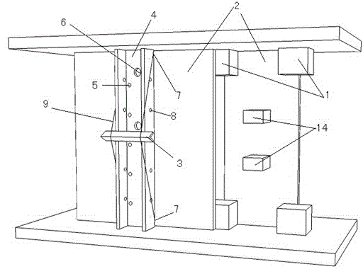
[0049] Prefabricated components: Prefabricated board 2 (length 3200, width 1200, thickness 20) is attached with glass fiber mesh, and the core material is filled with gypsum and cement (3:1). After mass production in the factory assembly line, it is delivered to the construction site, and the block connection The key 16 (length, width 100, thickness 180) is made of gypsum material in the factory assembly line after mass production, and then transported to the construction site. The six connecting keys 16 and the two prefabricated plates 2 are glued and firmly assembled into a cavity mold with an adhesive. The shape positioning key 1 is mass-produced in the factory assembly line using recycled hard plastic (square section, length 200, width 80, 180 two kinds, thickness 80).

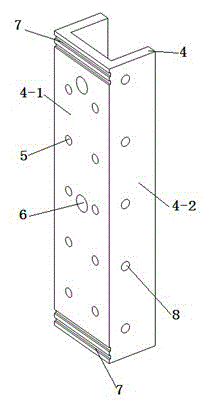
[0050] Construction tools: such as figure 2 with image 3 As shown, the pressure plate 4 is made of plastic steel (trough section: bottom plate 4-1 is 250 wide, side plate 4-2 is 150 high, plate thickness is ...

Embodiment 2

[0056] Such as Image 6 As shown, different from the first embodiment, the prefabricated plate 2 in this example uses a 10-thick thin plate. Because the plate is thin, a cable 9 is arranged every 500 or so along the height between the pressing plates 4. The cable adopts a ring-shaped, circumferential Length adjustable structure, the two ends of the cable 9 pass through the anchor hole 8 of the pressure plate 4 and are pinned with wooden bolts, and then the lock key 14 and the open key 13 are alternately arranged between the two strands of the cable 9 to make it shape In a diamond shape, such as Figure 13 with Figure 14 , The locking key 14 adopts a grooved plastic steel clip (length 30, width 30, height 15, wall thickness 5), and the opening key 13 adopts a plastic steel groove plate (length 200, width 50, height 20, wall thickness 5), both ends There is a card slot with a width of 10. Two force application keys 11 are arranged between the locking key 14 of the cable 9 ...

Embodiment 3

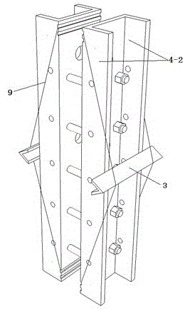
[0058] Such as Picture 9 As shown, the difference from the first embodiment is that the prefabricated plate 2 of this example uses a 10-thick thin plate. Because the plate is thin, for this reason, a self-balancing stiffener 10 is provided every 500 or so along the height between the pressure plates 4, and the stiffener 10 It adopts I-section plastic steel (length 1200, width 50, height 150, wall thickness 5), with 200 long serrated grooves (groove depth 10, width 20) on the lower sides of both ends, and the composite cable 9 on it adopts a ring, circumferential Long adjustable structure. The two ends of the stiffener 10 are fixed to the side plate 4-2 of the pressure plate 4, and the ring cable 9 is stuck in the zigzag concave-convex groove 7 at the two ends of the stiffener 10. Pin the cable 9 to the stiffener 10 with two balance keys 3 At one-third and two-thirds of the top surface, make the cable 9 bend and the stiffener 10 in a trapezoid shape, and then move the end of th...


PUM


Abstract

The invention provides a construction device for prefabricated surfaces and cast-in-place core-filled walls. Its advantage lies in that the pressure plate (4) used as the pressure applying device has the characteristics of sufficient rigidity and high strength. By setting stiffening ribs (10 ) or the cable (9) and the force-applying key (11) play a very good pre-stressing effect. The entire pressure device is easy to install and disassemble, flexible to configure, and has the function of force self-balancing. The pressing plate (4), stiffener (10), cable (9) and force key (11) are prefabricated in batches in the factory, which is conducive to simplifying installation and improving work efficiency. For large-area construction of thicker and higher height filled walls, its comprehensive economic index and construction period are better than the existing technology.

Description

technical field [0001] The invention relates to a building filling wall, in particular to a forming construction device for a prefabricated surface and a cast-in-place core filling wall. Background technique [0002] The building filling wall is the maintenance structure of the building, with a large amount and a wide area. Its sound insulation, heat insulation, strength, fire prevention, moisture resistance, waterproof and other properties directly affect the use performance and safety performance of the building. The invention "A self-balancing prefabricated surface and cast-in-place core-filled wall formwork (application number: 201310626576.4)" discloses a forming formwork for prefabricated surfaces and cast-in-place core-filled walls, in which the pressure device is mainly composed of Composed of a force key and a force cable, this pressure device is characterized by a simple structure, light and convenient, and is particularly effective for small-area construction, esp...

Claims


Application Information

Patent Timeline
Patent Type & Authority Patents(China)
IPC IPC(8): E04G11/08E04B2/86
Inventor 谢孟谢琦
Owner 盐城市双新建设投资有限公司
Why Eureka
Try Eureka