
Wind power self-lifting system

A wind power and magnetic technology, applied in the field of wind power self-lifting system, can solve the problems of increased lifting height, lowered hoisting accuracy, increased quality, etc., to achieve the effect of increasing load capacity and avoiding the decrease of adsorption force

Active Publication Date: 2014-02-26
CHANGCHUN UNIV OF SCI & TECH
View PDF6 Cites 10 Cited by
  • Summary
  • Abstract
  • Description
  • Claims
  • Application Information

AI Technical Summary

Problems solved by technology

Due to the height of the tower, it brings great inconvenience to maintenance personnel during equipment maintenance
[0003] During the maintenance of wind power equipment, there is a ladder connecting the bottom and top of the tower inside the tower. Maintenance personnel use bare hands to climb, which is not only a physical and psychological challenge for people, but also has the danger of falling
The equipment and parts are hoisted by a crane, but due to the increase in the mass of the heavy object and the increase in the lifting height, the hoisting accuracy is also reduced accordingly
Moreover, with the trend of large-scale generator sets, the methods of free-hand climbing and crane hoisting can no longer meet the requirements of maintenance operations

Method used


Image

  • Wind power self-lifting system
  • Wind power self-lifting system
  • Wind power self-lifting system

Examples


Embodiment Construction

[0025] Embodiments of the wind power self-lifting system of the present invention will be described below with reference to the accompanying drawings. Those skilled in the art would recognize that the described embodiments can be modified in various ways or combinations thereof without departing from the spirit and scope of the invention. Accordingly, the figures and the embodiments described below are illustrative in nature and not intended to limit the scope of the claims. In addition, in this specification, the drawings are schematic and do not necessarily draw the device of the present invention on an actual scale. Also, the same reference numerals denote the same parts in the respective drawings.

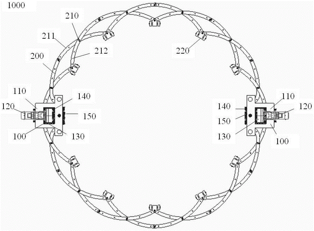
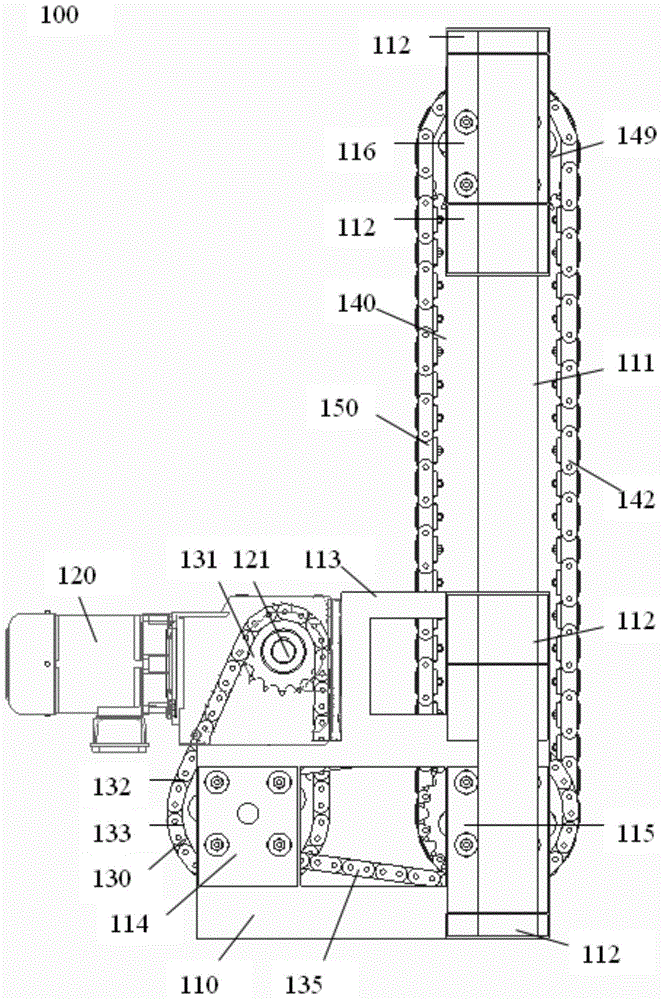
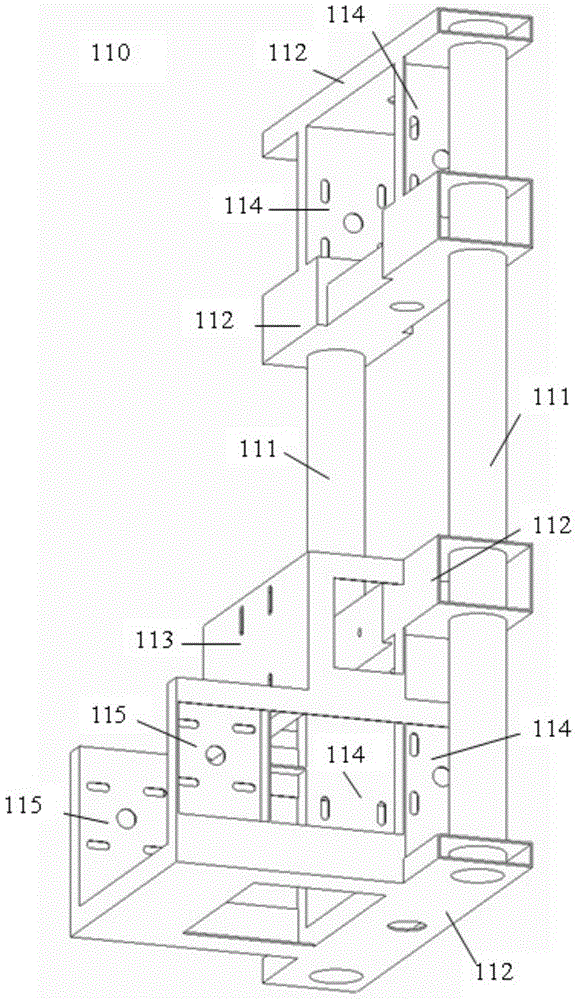
[0026] figure 1 It is a schematic diagram of the wind power self-lift system described in an embodiment of the present invention. figure 2 show figure 1 A schematic diagram of the magnetic wall-climbing vehicle of the wind power self-lift system. image 3 show figure 2 ...


PUM


Abstract

The invention provides a wind power self-lifting system comprising a plurality of magnetic wall-climbing carts (110) and a variable diameter truss (200). Each magnetic wall-climbing cart comprises a frame (110), a motor (120), a drive device (130), travelling mechanisms (140) and a magnetic sucker (150), wherein the motor is fixed on a support of the frame, the travelling mechanisms are tracked and composed of a plurality of sprockets and drive chains, and the magnetic sucker comprises a bracket, magnets and elastic blocks, and the magnets and the elastic blocks are disposed on the bracket at intervals. The variable diameter truss is hinged to the magnetic wall-climbing carts and comprises a plurality of crossing arms (210) with ends connected. Intersections of the crossing arms form a first circle, inner ends of the crossing arms form a second circle, and outer ends of the crossing arms form a third circle; the circles are concentric. Each crossing arms include wide arms (211) and narrow arms (212). Magnetic guide carts are fixed at the inner ends of the crossing arms.

Description

technical field [0001] The invention relates to a wind power self-lifting system, in particular to a wind power self-lifting system for moving in the vertical direction of a wind turbine tower wall. Background technique [0002] As a clean renewable energy, wind energy has been paid more and more attention. Wind energy can be converted into electricity using wind power plants, which require neither fuel nor radiation or air pollution. The devices required for wind power generation mainly include wind rotors, generator sets and towers. The wind drives the wind rotor to rotate and converts the kinetic energy of the wind into mechanical energy. The generator set converts the mechanical energy obtained by the wind rotor into electrical energy. The tower is the frame that supports the wind rotor and the generator set. The material of the tube is steel, and the height of the tower is set at 80-100 meters or more than 100 meters. As the height of the tower increases, the diameter...

Claims


Application Information

Patent Timeline
IPC IPC(8): F03D11/00B62D57/024
CPCY02E10/722Y02E10/72Y02E10/728
Inventor 史国权曹国华吕琼莹孟宪宇梅玉石
Owner CHANGCHUN UNIV OF SCI & TECH
Learn More