
Loading machine anti-bumping and vibrating shock mitigation system

A vibration-damping system and anti-turbulence technology, which is applied to gas shock absorbers and other directions, can solve problems such as difficulty in diagnosing faults, difficult maintenance, and long service periods, and achieve the effects of easy elimination, remarkable effect and simple structure.

Active Publication Date: 2015-07-22
XCMG CONSTR MACHINERY
View PDF7 Cites 0 Cited by
  • Summary
  • Abstract
  • Description
  • Claims
  • Application Information

AI Technical Summary

Problems solved by technology

However, the selection of materials for hydraulic accumulators and related hydraulic valve components is relatively strict, the requirements for processing accuracy are very high, and the requirements for manufacturing technology are relatively advanced. A slight processing error may lead to the failure of the whole machine, so foreign products are generally used. brand; the hydraulic damping system consists of many valve body components, and all of them are under high pressure, which has poor reliability and is also dangerous; when the hydraulic damping system fails, it is often difficult to judge the fault, and in During maintenance, it is often necessary to drain the hydraulic oil to release the high pressure of the hydraulic system in order to maintain
In the process of releasing, it will inevitably lead to the leakage of hydraulic oil, so it will cause pollution to the environment, the maintenance is difficult, and the service cycle is long. Therefore, the comprehensive use cost of the entire hydraulic vibration damping system is expensive

Method used


Image

  • Loading machine anti-bumping and vibrating shock mitigation system
  • Loading machine anti-bumping and vibrating shock mitigation system
  • Loading machine anti-bumping and vibrating shock mitigation system

Examples


Embodiment

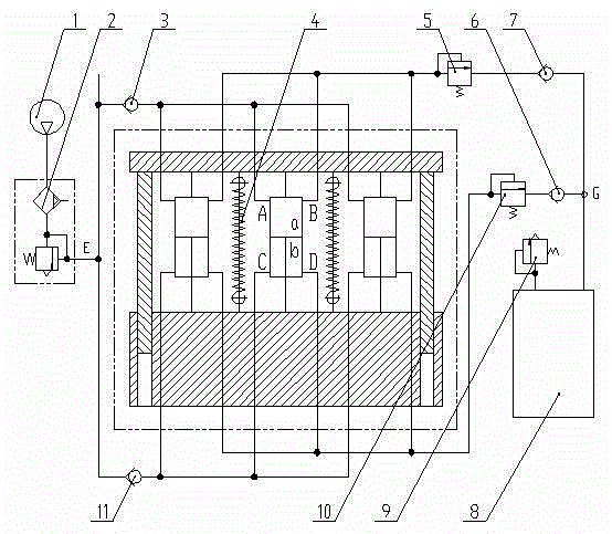
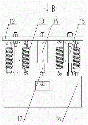
[0016] Embodiment: The air outlet of the air pump 1 is connected to the air inlet of the combined valve 2, the air outlet E of the combined valve 2 is connected to the A port of the cylinder block 14 in the damping mechanism 4 through the first one-way valve 3, and the air outlet E in the damping mechanism 4 The B port of the cylinder block 14 is connected with the air inlet of the first relief valve 5, the outlet of the first relief valve 5 is connected with the air inlet of the air storage tank 8 through the third one-way valve 7, and the air outlet of the combined valve 2 The other path of E is connected to the C port of the cylinder block 14 in the damping mechanism 4 through the fourth one-way valve 11, and the D port of the cylinder block 14 in the damping mechanism 4 is connected to the air inlet of the second relief valve 10. The outlet of the second overflow valve 10 is connected to the air inlet of the air storage tank 8 through the second one-way valve 6, the air out...


PUM


Abstract

The invention discloses a loading machine anti-bumping and vibrating shock mitigation system. An air pump outlet is connected with combination valves inlets, an combination valves outlet E is connected with an A mouth of a cylinder body in the shock mitigation system via a first one-way valve, a B mouth of the cylinder body of the shock mitigation system is connected with an inlet of a first overflow valve, an outlet of the first overflow valve is connected with an inlet of an air cylinder via a third one-way valve, the other path of the combination valves outlet E is connected with a C mouth of the cylinder body in the shock mitigation system via a forth one-way valve, a D mouth of the cylinder body in the shock mitigation system is connected with an air inlet of the second overflow valve, the outlet of the second overflow valve is connected with the air inlet of the air cylinder via the second one-way valve, the outlet of the air cylinder is connected with an air inlet of a safety valve, a rear frame of the shock mitigation system is connected with the air cylinder, the air cylinder is connected with a balance weight via an air cylinder piston rod, and a spring and a guiding rod are arranged between the rear frame and the balance weight. The loading machine anti-bumping and vibrating shock mitigation system is simple in structure, high in reliability, few in failure and easy to eliminate failure, so that affordable cost is low.

Description

technical field [0001] The invention relates to a vibration damping system for a loader, in particular to a vibration damping system for preventing the periodic vibration of the loader from pitching forward and backward. Background technique [0002] When the loader is driving, due to the different weights carried by the front and rear drive axles, the tires will deform differently, resulting in different distances from the center axis of the front and rear tires to the ground. In order to increase traction, the loader adopts four-wheel drive. , The speed transmitted by the engine to the front and rear axles is the same, which causes the speed of the front and rear wheels to be different when the whole machine is running. Assuming that the whole machine is empty, the speed of the front wheels will be greater than that of the rear wheels. As a result, when the front axle tires are rolling, the rear axle tires will slide forward due to the traction of the front wheels at the s...

Claims


Application Information

Patent Timeline
Patent Type & Authority Patents(China)
IPC IPC(8): F16F9/02
Inventor 王小虎沈勇韩标郭军胜张爱霞程然黄新钟俊伟
Owner XCMG CONSTR MACHINERY
Learn More