Furnace wall gun copper box cooling method

A cooling method and furnace wall technology, which is applied in the field of metallurgy, can solve problems such as cracks on the side wall of copper boxes, water leakage, uneven cooling, etc., and achieve the effects of improving poor cooling effects, reducing losses, and reducing production heat shutdowns

Inactive Publication Date: 2014-02-26
SHANXI TAIGANG STAINLESS STEEL CO LTD
View PDF5 Cites 0 Cited by
  • Summary
  • Abstract
  • Description
  • Claims
  • Application Information

AI Technical Summary

Problems solved by technology

During the use of the copper box cooled by cooling water on the side wall, the cooling around the edge and center of the side wall is also uneven. At the same time, coupled with the periodic changes in the cold and hot operation of the electric arc furnace, the side wall of the copper box is prone to cracks and water leakage.

Method used


Image

  • Furnace wall gun copper box cooling method
  • Furnace wall gun copper box cooling method

Examples


Embodiment 1

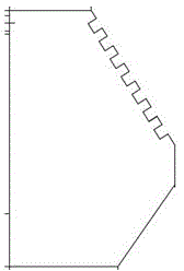
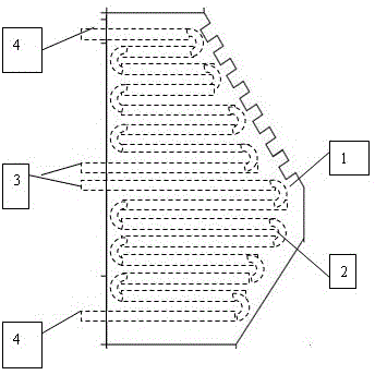
[0018] Example 1: 90t all-scrap stainless steel smelting, three sets of multifunctional furnace wall oxygen lances are installed on the furnace wall, 2# and 3# side walls are cooled by cooling water, and the 1# side wall is improved to be cooled by compressed air. That is, two copper tubes are welded on the 1# side wall 1 as the cooling tube 2, and the two copper tubes are bent into a serpentine shape and arranged horizontally on the 1# side wall ( figure 2 shown).

[0019] Compressed air enters from two air inlets 3 and is discharged through two air outlets 4, and cools the side walls of 2# and 3# through compressed air.

[0020] In this embodiment, compressed air is used to cool the 1# side wall, and one furnace (500 furnaces) cracks and leaks air once, and the cooling effect is obvious.

[0021] The implementation effect of the present invention is compared with the prior art: 90 tons of scrap steel and stainless steel are smelted, three sets of multifunctional furnace wa...

Embodiment 2

[0022] Embodiment 2: In this embodiment, 3 cooling pipes are used on the 1# side wall, that is, 3 air inlets and 3 air outlets are set; compressed air enters from 3 air inlets, and is discharged from 3 air outlets. Others are the same as in Embodiment 1.

[0023] In this embodiment, one furnace (500 furnaces) has 0 cracks and leaks, and the cooling effect is obvious.

[0024] The implementation effect of the present invention is compared with the prior art: 90 tons of scrap steel and stainless steel are smelted, three sets of multifunctional furnace wall oxygen lances are installed on the furnace wall, the side walls of 2# and 3# are cooled by cooling water, and the side wall of 1# copper box is cooled by water One furnace service (500 furnaces) cracked and leaked water 3 times. When the side wall is not cooled, one furnace (500 furnaces) burns through 4 times.


PUM


Abstract

Disclosed is a furnace wall gun copper box cooling method. The method is characterized by including that (1) equipment improvement is performed on the side wall of a copper box of a furnace wall gun, in other words, at least two cooling pipes are welded to the inner side of an outer copper plate of the side wall of the copper box of the furnace wall gun, wherein each cooling pipe is provided with an air inlet and an air outlet, cooling pipe orifices in the middle of the side wall of the copper box are set as the air inlets, and cooling pipe orifices in the upper portion and the lower portion of the side wall of the copper box are set as the air outlets; (2) compressed air enters from the air inlets in the middle of the side wall of the copper box and is discharged from the air outlets in the upper portion and the lower portion of the side wall of the copper box, and cooling is performed via the compressed air under the pressure of 2.0-2.8MPa and with the flow more than or equal to 4000Nm3/h. Cooling effect is regulated by increasing and decreasing the air circulation inlets and outlets and the air circulation speed. Thus, frequent water leakage caused by cooling of cooling water as well as long-time thermal shutdown and major potential safety hazards caused by water leakage are avoided.

Description

technical field [0001] The invention belongs to the field of metallurgy, and in particular relates to a method for cooling a furnace wall gun copper box. Background technique [0002] In modern electric arc furnace smelting technology, furnace wall cluster oxygen lance technology and furnace wall burner technology have been widely used as means of high-efficiency and energy-saving production of electric arc furnace. [0003] Usually this type of furnace wall gun is installed on the furnace wall using a water-cooled copper box as a cooling support. The structure of the copper box is cooled by cooling water through the front, figure 1 As shown, the side wall is divided into two types: uncooled or cooled with cooling water. [0004] In actual use, due to arc erosion and periodic cooling changes in electric furnace smelting, the side wall of the water-cooled copper box facing the hot zone of the electric furnace is prone to frequent cracks and water leakage (cooling water pass...

Claims


Application Information

Patent Timeline
Patent Type & Authority Applications(China)
IPC IPC(8): F27D9/00
Inventor 刘睿智童永亮武鹏朱晓辉
Owner SHANXI TAIGANG STAINLESS STEEL CO LTD
Why Eureka
Try Eureka