Monitoring apparatus and method for ESR and C of boost PFC converter

A monitoring device and converter technology, applied in measurement devices, power supply testing, instruments, etc., can solve the problems of increasing costs, time-consuming and laborious replacement of components or repairing power supplies, and increased costs, and achieve the effect of reducing difficulty

Active Publication Date: 2014-02-26
NANJING UNIV OF SCI & TECH
View PDF8 Cites 32 Cited by
  • Summary
  • Abstract
  • Description
  • Claims
  • Application Information

AI Technical Summary

Problems solved by technology

As an important part of the electronic equipment system, the short life and failure of the capacitor will cause very serious consequences, as follows: 1. Interrupt the normal operation of the entire system, causing huge adverse effects and losses, especially in production, transportation, aviation Aerospace, military and national defense and other fields; 2. The failure of the capacitor will produce a "chain reaction", causing damage to other components in the power supply; 3. It is time-consuming and laborious to replace components or repair the power supply, which not only affects the efficiency of production and life, but also increases the cost; 4. Most of the time, the entire electronic device is replaced or discarded just because of the failure of the power supply, which not only causes huge cost increase and waste, but also generates electronic waste and causes environmental pollution

Method used


Image

  • Monitoring apparatus and method for ESR and C of boost PFC converter
  • Monitoring apparatus and method for ESR and C of boost PFC converter
  • Monitoring apparatus and method for ESR and C of boost PFC converter

Examples


Embodiment Construction

[0022] The present invention will be described in further detail below in conjunction with the accompanying drawings and specific embodiments.

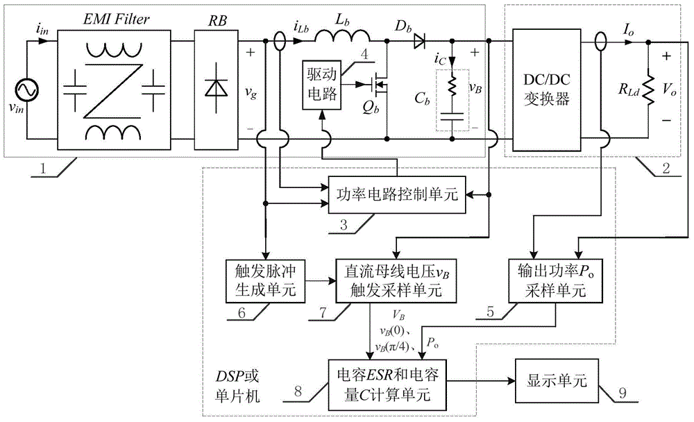
[0023] The invention designs a device and a method for on-line monitoring of the output filter capacitor ESR and C of a Boost PFC converter.

[0024] 1. Theoretical derivation:

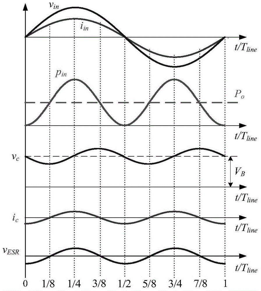
[0025] figure 1 The working waveform of the Boost PFC converter in the power frequency cycle is given.

[0026] Define the input AC voltage v in The expression is:

[0027] v in (t)=V msin ωt (1)

[0028] If the power factor is 1, the input AC current i in The expression is:

[0029] i in (t)=I m sin ωt (2)

[0030] where V m is the magnitude of the input AC voltage, I m is the amplitude of the input AC current, and ω is the angular frequency of the input AC voltage.

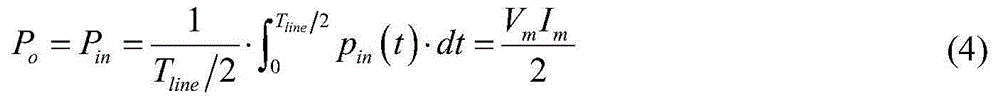
[0031] The input power p can be obtained from formulas (1) and (2) in The expression is as follows:

[0032] p in (t)=v in (t)·i in (t)=V m I m sin 2 ωt (3)

[0033] Assu...


PUM


Abstract

The invention discloses a monitoring apparatus and method for equivalent series resistance (ESR) and capacitance (C) of a boost power factor correction (PFC) converter. The apparatus comprises a boost PFC converter main power circuit, a DC/DC converter unit, a power circuit control unit, a drive circuit, an output power Po sampling unit, a trigger pulse generating unit, a direct-current bus voltage V trigger sampling unit, a capacitor ESR and a capacitance C computing unit, and a display unit. The trigger pulse generating unit monitors an input voltage after rectification so as to obtain a sampling trigger pulse; the direct-current bus voltage trigger sampling unit monitors an average voltage value and obtains a voltage instantaneous value according to the trigger pulse sampling; the output power Po sampling unit monitors an output power of the converter; the data are sent to the capacitor ESR and a capacitance C computing unit and thus the current ESR value and the current C value of the output filter capacitor of the boost PFC converter are obtained; and the display unit carries out real-time displaying. According to the invention, on-line monitoring of the ESR and C values of the capacitor can be realized; the normal work of the converter is not influenced; and the basis is provided for service life prediction of the capacitor and the power supply.

Description

technical field [0001] The invention belongs to the technical field of monitoring in electric energy conversion devices, in particular to a monitoring device and method for output capacitors ESR and C of a step-up PFC converter. Background technique [0002] Generally speaking, most electronic equipment needs DC power of a certain voltage and power when running, and in most cases, the mains power supply for direct power supply is a sinusoidal AC voltage, generally 220V / 50Hz (115V / 400Hz). Therefore, it is necessary to transform the alternating current into direct current to meet the needs of electronic equipment. Among them, the power factor correction (Power Factor Correction, PFC) converter uses a power electronic circuit to make the input current waveform sinusoidal and in phase with the input voltage to reduce harmonic pollution to the power grid. At the same time, it also makes the output voltage relatively stable, and provides a relatively stable DC input voltage for...

Claims


Application Information

Patent Timeline
Patent Type & Authority Applications(China)
IPC IPC(8): G01R31/40G01R27/26
Inventor 姚凯唐伟杰吕建国孟庆赛付晓勇毕晓鹏李强
Owner NANJING UNIV OF SCI & TECH
Why Eureka
Try Eureka