

Optical device
An optical device and optical system technology, applied in optics, optical components, nonlinear optics, etc., can solve the problem of increasing optical coupling loss, and achieve the effect of reducing coupling loss and improving practicability
- Summary
- Abstract
- Description
- Claims
- Application Information
AI Technical Summary
Problems solved by technology
Method used
Image

Examples
no. 1 example
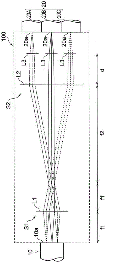
[0047] First, refer to figure 2 The optical device 100 according to the first embodiment will be described.
[0048] Such as figure 2 As shown, the optical device 100 is a device that couples a multi-core optical fiber 10 (optical element) with a single-core optical fiber 20 (another optical component) to transmit a single-mode optical signal (wavelength multiplexed signal), and constructs into a first optical system S1 and a second optical system S2. Hereinafter, an optical device using a multi-core optical fiber as an optical element and included in the present invention is referred to as a multi-core fiber coupling device.
[0049] The multi-core optical fiber 10 used in this embodiment is an optical element that includes a plurality of light output portions having optical axes parallel to each other; specifically, the multi-core optical fiber 10 has seven cores area, and emit 7 beams from the exit end face 10a ( figure 2 Only 3 beams are shown in the cross-sectional...
no. 2 example
[0063] Then, refer to Figure 4 A multi-core fiber coupling device 100A according to a second embodiment will be described.
[0064] Such as Figure 4 As shown, the multi-core fiber coupling device 100A differs from the multi-core fiber coupling device 100 according to the first embodiment only in the configuration of the second optical system S2.
[0065] The second optical system S2 of the multi-core fiber coupling device 100A is composed of lens arrays L4 to L6. The lens array consists of 7 lenses ( Figure 4 The cross-sectional view of shows only 3 lenses L4 to L6) constituted so as to correspond to 7 light beams respectively. Each of the seven lenses L4 to L6 of the second optical system S2 has a focal length of f1, which is equal to the focal length of the condenser lens L1 of the first optical system S1.
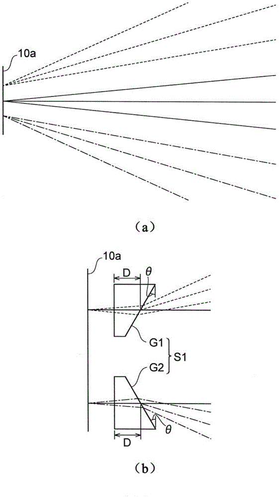
[0066] Therefore, similarly to the first embodiment, the dispersion angle θ on the end face 10a of the multi-core optical fiber 10 出射 Equal to the dispersion ang...
no. 3 example
[0070] Refer below Figure 6 to Figure 8 A multi-core fiber coupling device 100B according to a third embodiment will be described.
[0071] Such as Figure 6 As shown, the multi-core fiber coupling device 100B differs from the multi-core fiber coupling device 100A according to the second embodiment described above only in the configuration of the second optical system S2. That is to say, the second optical system S2 of the multi-core fiber coupling device 100B is composed of a lens array; in this lens array, seven lens sheets L7 to L9 are combined instead of seven lenses L4 to L6.
[0072] This multi-core fiber coupling device 100B can also obtain the same or similar effects as the multi-core fiber coupling device 100 according to the first embodiment.
[0073] Here, in the case of using a more realistic lens rather than an ideal lens, the aberration of the lens needs to be considered.
[0074] Such as Figure 7 As shown, the multiple light beams passing through the lens ...
PUM
| Property | Measurement | Unit |
|---|---|---|
| length | aaaaa | aaaaa |
| length | aaaaa | aaaaa |
| diameter | aaaaa | aaaaa |
Abstract
Description
Claims
Application Information