
Eureka
For R&D, Eureka makes reading and utilizing patents & technical documents easy.
Eureka AIR
Designed for self-driven R&D workflows. Generate viable solutions, solve complex R&D challenges, empower your innovation with AI.

Eureka Materials
Designed for material experts only. Revolutionize your material R&D, from search, analyze, to developing new materials.

TechResearch
Generate reliable direction feasibility study reports for your R&D in just a few steps.

TechSeek
Discover and master advanced knowledge NOW. Basics, ideas, possibilities, all at once.

TechMind
As an expert in R&D Theories, TechMind can generates customized viable solutions instantly.

TechRisk
Analyze your overall solution with one click, know your potential R&D risks in advance.

TechMonitor
Get weekly tech updates, stay abreast of the latest tech innovations and key insights.
Improved multi-side contact electronic building block
An electronic building block, surface contact technology, applied in toys, instruments, entertainment and other directions, can solve the practical and interesting bottlenecks of electronic building blocks, unable to create a splicing method, unable to splicing out graphics and other problems
- Summary
- Abstract
- Description
- Claims
- Application Information
AI Technical Summary
Problems solved by technology
Method used
Image

Examples
Embodiment 1
[0035] Embodiment one, such as Figure 5 shown.
[0036] In this embodiment, inner cavities 1121 are provided at both ends of the splicing boss 11 ; The inner cavity 1121 is also provided with a positioning post (not necessary) that matches the ring of the annular magnet 1120, and the annular magnet 1120 can rotate freely around the axial direction; after the annular magnet 1120 is radially magnetized The magnetism on its surface is an S-N relationship. When the two faces of the two blocks are close together, as if the side is an N-S pole, the ring-shaped magnet 1120 is mutually repulsive. At this time, the ring-shaped magnet 1120 will be in the inner cavity. 1121 internal rotation, self-adjust to the position where the magnetic poles attract each other.
Embodiment 2
[0037]Embodiment two, such as Figure 7 shown.
[0038] In this embodiment, inner cavities 1121 are provided at both ends of the splicing boss 11 ; the magnetic attraction assembly includes radially magnetized magnets movable in the inner cavities, and the magnets are spherical magnets 1123 . The spherical magnet 1123 can rotate freely; after the radial magnetization of the spherical magnet 1123, the magnetism on its surface is an S-N relationship. At this time, the spherical magnet 1123 will rotate in the inner cavity 1121 and adjust itself to a position where the magnetic poles attract each other.
Embodiment 3
[0039] Embodiment three, such as Figure 8 shown.
[0040] In this embodiment, inner cavities 1121 are provided at both ends of the splicing boss 11; Cylindrical magnet 1124 can rotate freely around the axial direction; the magnetism on the surface of cylindrical magnet 1124 after radial magnetization is S-N relationship. The magnets 1124 are mutually repulsive. At this time, the cylindrical magnet 1124 will rotate in the inner cavity 1121 and adjust itself to a position where the magnetic poles attract each other.
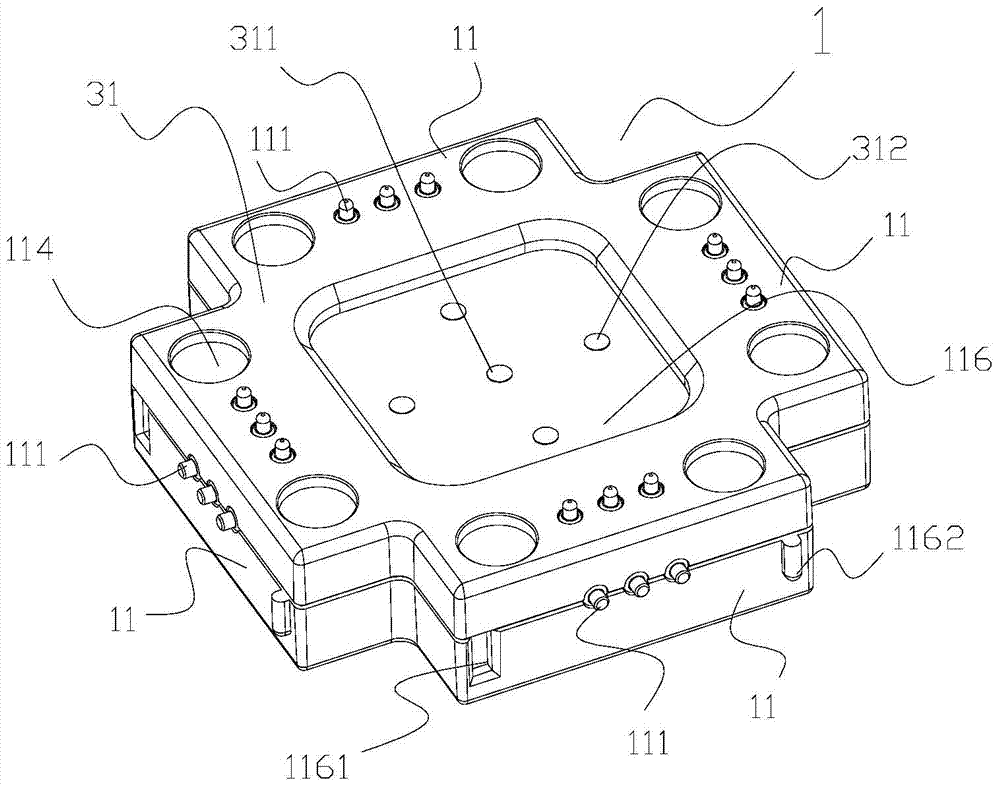
[0041] combine Figure 9 and 10 as well as Figure 11 and 12 , explain in detail the structure of the electrical connector in the specific embodiment. The electrical connector 111 is at least one connection contact on the outer side and the upper end surface of the splicing boss 11, and in a preferred embodiment, it is three connection contacts, and the connection contacts are spring probes or shrapnel; The connecting piece 111 is at least one contact end o...
PUM
 Abstract
Description
Claims
Application Information
 - R&D Engineer
- R&D Manager
- IP Professional
- Industry Leading Data Capabilities
- Powerful AI technology
- Patent DNA Extraction
Browse by: Latest US Patents, China's latest patents, Technical Efficacy Thesaurus, Application Domain, Technology Topic, Popular Technical Reports.
© 2024 PatSnap. All rights reserved.Legal|Privacy policy|Modern Slavery Act Transparency Statement|Sitemap|About US| Contact US: help@patsnap.com