Workpiece surface wiping device and workpiece surface wiping method

A workpiece surface and workpiece technology, applied in the field of workpiece surface wiping devices, can solve the problems of low efficiency, poor cleaning effect, and high cost of ultrasonic cleaning equipment

Inactive Publication Date: 2014-03-05
株式会社雷恩工业
View PDF8 Cites 45 Cited by
  • Summary
  • Abstract
  • Description
  • Claims
  • Application Information

AI Technical Summary

Problems solved by technology

[0011] 1. The main disadvantage of the manual cleaning method is that it requires a lot of manpower, and the efficiency is low, and the cleaning effect is not good (the dirt will be missed; if the wiping cloth is wiped back and forth, it will cause secondary pollution; It may be replaced in time, and it is often replaced when the dirt has accumulated to a certain extent, and it is also likely to cause secondary pollution), and the use of sticky sticks is easy to cause scratches and the quality of the workpiece is unstable
[0012] 2. The disadvantages of using ultrasonic cleaning equipment for cleaning are: the cost of ultrasonic cleaning equipment is high, the area is large, high temperature and high pressure, and residual moisture is easy to affect the quality of the workpiece
[0013] 3. The disadvantages of using gas or gas ion cleaning are: high equipment cost, large area, and the ion emission source itself may be a pollution source that produces dirty particles, so the workpiece may still remain after cleaning with the ion emission source. Residual particles affect the quality of the workpiece
[0014] 4. The disadvantage of using the cleaning roller for cleaning is that the dirt attached to the surface of the cleaning roller needs to be transferred in time, otherwise it will affect the subsequent cleaning, so it is necessary to set a sticky paper roll
Similarly, the dirt attached to the sticky paper roll needs to be transferred in time, otherwise it will affect the transfer of dirt attached to the surface of the cleaning roller. Therefore, it is necessary to set up a sticky paper cutting device or a sticky paper winding device so that the sticky paper roll The dust paper is cut, stripped and collected in time, and the structure is complex; moreover, the surface of the workpiece looks flat, but under the magnifying glass, it can be seen that it has grooves. For the dirt in these grooves, cleaning The roller cannot be cleaned; in addition, the dirt on the cleaning roller cannot be completely transferred away, there will always be some residue, and it is impossible to replace the cleaning roller after one rotation, and it will often run for a period of time (that is, many rotations) before replacement. It is easy to cause incomplete cleaning and affect the quality of the workpiece

Method used


Image

  • Workpiece surface wiping device and workpiece surface wiping method
  • Workpiece surface wiping device and workpiece surface wiping method
  • Workpiece surface wiping device and workpiece surface wiping method

Examples


Embodiment Construction

[0089] In order to understand the technical content of the present invention more clearly, the following examples are given in detail.

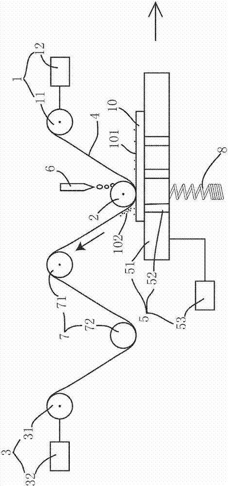
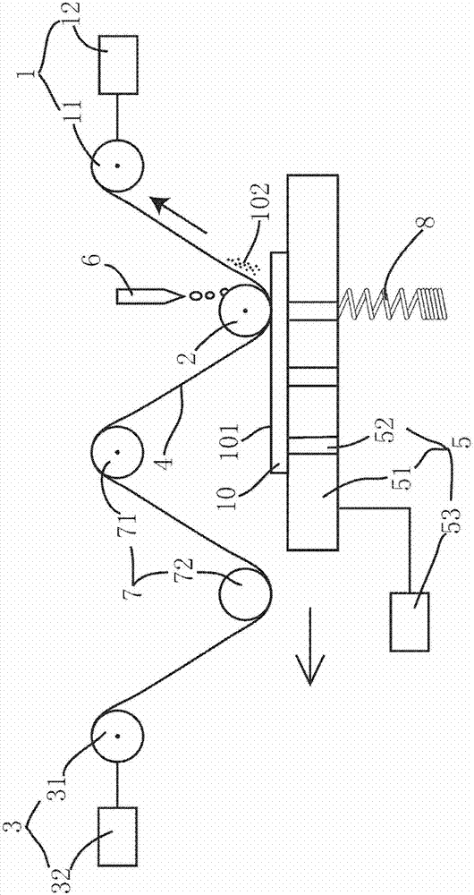
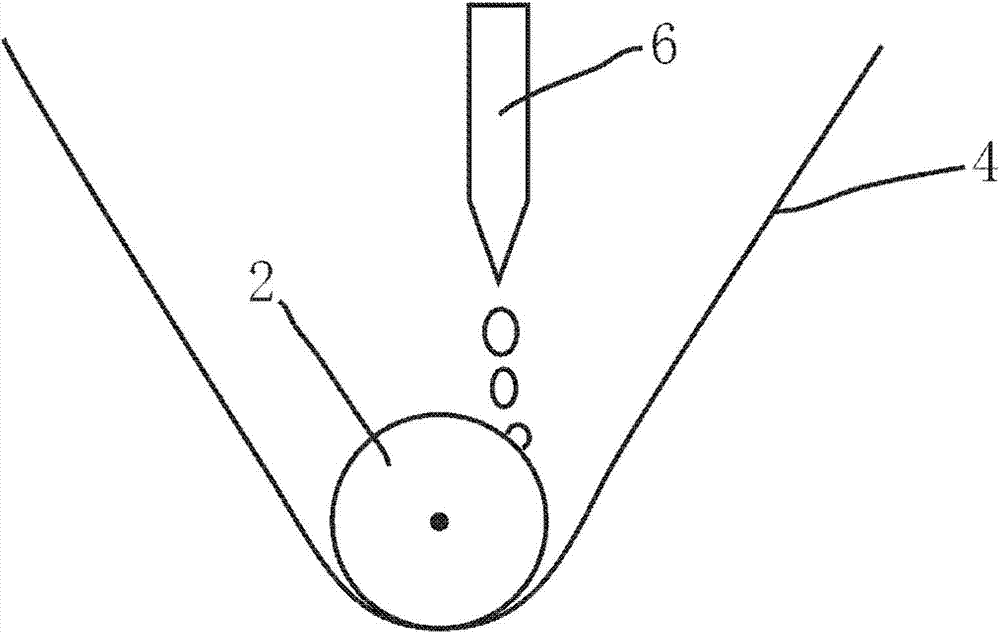
[0090] see figure 1 , figure 2 , image 3 and Figure 5 , in a specific embodiment of the present invention, the workpiece surface wiping device of the present invention includes an unwinding mechanism 1, a pressing roller 2, a winding mechanism 3, a flexible cleaning object 4 and a workpiece fixing mechanism 5, and the pressing roller 2 is located at the The downstream of the unwinding mechanism 1 is arranged axially parallel to the unwinding mechanism 1; the winding mechanism 3 is located downstream of the pressing roller 2 and arranged axially parallel to the pressing roller 2; the flexible cleaning One end of the object 4 is wound on the unwinding mechanism 1, and the other end of the flexible cleaning object 4 is wound on the winding mechanism 3 after passing through the pressing roller 2; the workpiece fixing mechanism 5 is used for...


PUM


Abstract

The invention provides a workpiece surface wiping device. An unwinding mechanism, a press roller and a winding mechanism are arranged in sequence in a mutual axial parallel manner. One end of a flexible cleaning object is wound on the unwinding mechanism while the other end of the same is wound on the winding mechanism after being wound on the press roller. A workpiece fixing mechanism is used for fixing a to-be-cleaned workpiece and arranged with the press roller at an interval, so that the flexible cleaning object wound on the press roller is located between the workpiece fixing mechanism and the press roller and clings to the press roller; the workpiece fixing mechanism is arranged movably relatively to the press roller, so that when the to-be-cleaned workpiece is fixed on the workpiece fixing mechanism, a to-be-cleaned surface of the workpiece is in contact with the flexible cleaning object wound on the press roller and moves relatively to the flexible cleaning object so as to contact with the flexible cleaning object wound on the press roller from one end to the other end successively. The invention further provides a workpiece surface wiping method. The workpiece surface wiping device is simple in structure, low in cost, small in occupied area, free of large amount of labor input, high in efficiency, good in cleaning effect and stable in workpiece quality, and can not cause scratch to the workpiece.

Description

technical field [0001] The invention relates to the technical field of workpiece cleaning, in particular to the technical field of workpiece surface cleaning, in particular to a workpiece surface wiping device and a workpiece surface wiping method. Background technique [0002] The surface of the workpiece produced in the factory is usually dirty, such as oil, debris, dust, etc., whether it is directly packaged as a product or assembled with other workpieces to form a component, it needs to be cleaned to make the product appear clean Appearance, so as to attract customers, or make components perform well, and enhance the performance of the final product. [0003] For example, in the manufacturing process of a thin film transistor liquid crystal display (TFT-LCD), it is necessary to assemble the liquid crystal panel and the backlight module. After the liquid crystal panel is stacked on the correct position above the backlight module, it is fitted and fixed. And if during the...

Claims


Application Information

Patent Timeline
Patent Type & Authority Applications(China)
IPC IPC(8): B08B1/00B08B13/00B65H37/00B65H23/04
CPCB08B1/006B08B1/008
Inventor 高桑利宗
Owner 株式会社雷恩工业
Why Eureka
Try Eureka