Sliding rail type knife rest

A technology of slide rails and tool holders, which is applied in the direction of tool holders, etc., can solve the problems of large rotary diameter of the cutter head, slow rotation of tool changes, and shortened service life of tool holders, achieving less tool change times, reduced tool change times, The effect of increasing the number of stations

Inactive Publication Date: 2014-03-05
苏州康菲特自动化科技有限公司
View PDF10 Cites 0 Cited by
  • Summary
  • Abstract
  • Description
  • Claims
  • Application Information

AI Technical Summary

Problems solved by technology

However, for the processing of specific products, the main cutting tools used are mostly specific two or three, and other tools are usually interspersed between the two cutting processes of the same tool for cutting, requiring frequent tool changes, but The rotary diameter of the cutter head is large, and the rotary tool change is slow, and the frequent rotary tool change also greatly shortens the service life of the tool holder

Method used


Image

  • Sliding rail type knife rest
  • Sliding rail type knife rest

Examples


Embodiment Construction

[0020] The technical solutions of the present invention will be further described below in conjunction with the accompanying drawings and preferred embodiments of the present invention.

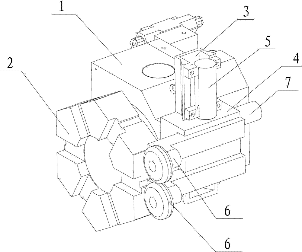
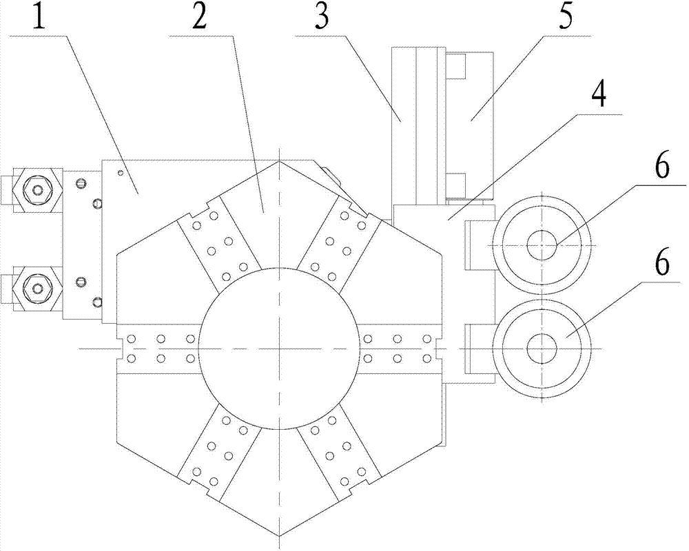
[0021] see figure 1 , figure 2 The slide rail type tool post shown includes a tool holder 1 and a rotary cutter head 2 rotatably arranged at the front end of the tool holder 1. There are 6 stations on the rotary cutter head 2, and knives are respectively installed on the 6 stations. , the stations on the rotary cutter head 2 can be replaced by driving the rotary cutter head 2 to rotate. The knife rest also includes a slide rail 3 fixed on the side of the knife rest 1, the slide rail 3 extends in the vertical direction, the slide rail 3 is provided with a sliding seat 4, and the slide seat 4 is detachably provided with two Knife handle 6, two knife handles 6 are arranged along the up and down direction, and the axis lines of the two knife handles 6 are all parallel to the axis line of...


PUM


Abstract

The invention discloses a sliding rail type knife rest which comprises a knife apron and a rotary knife disc arranged at the front end of the knife apron in a rotary mode and provided with a plurality of stations. The knife rest further comprises sliding rails fixed to the lateral portion of the knife apron and distributed in the vertical direction, a sliding base which is arranged on the sliding rails and is capable of sliding in the vertical direction, a driving mechanism arranged on the knife apron and used for driving the sliding base to slide in the vertical direction and a locking mechanism used for locking the sliding base on the sliding rails, at least two knife handles are detachably arranged on the sliding base, and the knife handles are sequentially arranged in the vertical direction. Knives high in replacement frequency in the process of machining are installed on the knife handles, the station switching on the knife handles can be achieved through vertical sliding of the sliding base and movement of the knife rest so that knife replacement can be achieved and knife replacement can be rapid. Knives with low replacement frequency are installed on the rotary knife disc, so that a large amount of knife replacement time is saved and the production efficiency of cutting is improved.

Description

[0001] technical field [0002] The invention relates to a slide rail type tool rest. [0003] Background technique [0004] Traditional CNC machine tools are usually equipped with a tool holder with a rotating cutter head. The cutter head has multiple positions of tools, and the positions are switched by rotating the cutter head, so that the tools of different positions can be switched according to processing needs. However, for the processing of specific products, the main cutting tools used are mostly specific two or three, and other tools are usually interspersed between the two cutting processes of the same tool for cutting, requiring frequent tool changes, but The rotary diameter of the cutter head is large, and the rotary tool change is slow, and the frequent rotary tool change also greatly shortens the service life of the tool holder. [0005] Contents of the invention [0006] The object of the present invention is to provide a slide-rail type tool holder capa...

Claims


Application Information

Patent Timeline
IPC IPC(8): B23B29/32
CPCB23B29/32
Inventor 薛荣洲
Owner 苏州康菲特自动化科技有限公司
Why Eureka
Try Eureka