
Fairing structure for pylon of aircraft with wing-mounted layout

A fairing and layout technology, which is applied in the field of aircraft aerodynamic shape design, can solve problems such as adverse effects of airflow, inability to reflect practical value, and inability to achieve deflection of hanging cross-sections, so as to reduce adverse effects, avoid airframe structure weight, reduce The effect of aircraft manufacturing and maintenance costs

Active Publication Date: 2014-03-05
COMAC +1
View PDF7 Cites 3 Cited by
  • Summary
  • Abstract
  • Description
  • Claims
  • Application Information

AI Technical Summary

Problems solved by technology

When the installation space is small, the solution cannot reflect the practical value
Because when the installation space is small, there is almost no complete airfoil in the suspension cross-section, and the deflection of the suspension cross-section expressed by the complete airfoil cannot be realized
Moreover, this solution may have an adverse effect on the airflow at the intersection of the aircraft suspension and the leading edge of the wing towards the wingtip.

Method used


Image

  • Fairing structure for pylon of aircraft with wing-mounted layout
  • Fairing structure for pylon of aircraft with wing-mounted layout
  • Fairing structure for pylon of aircraft with wing-mounted layout

Examples


Embodiment Construction

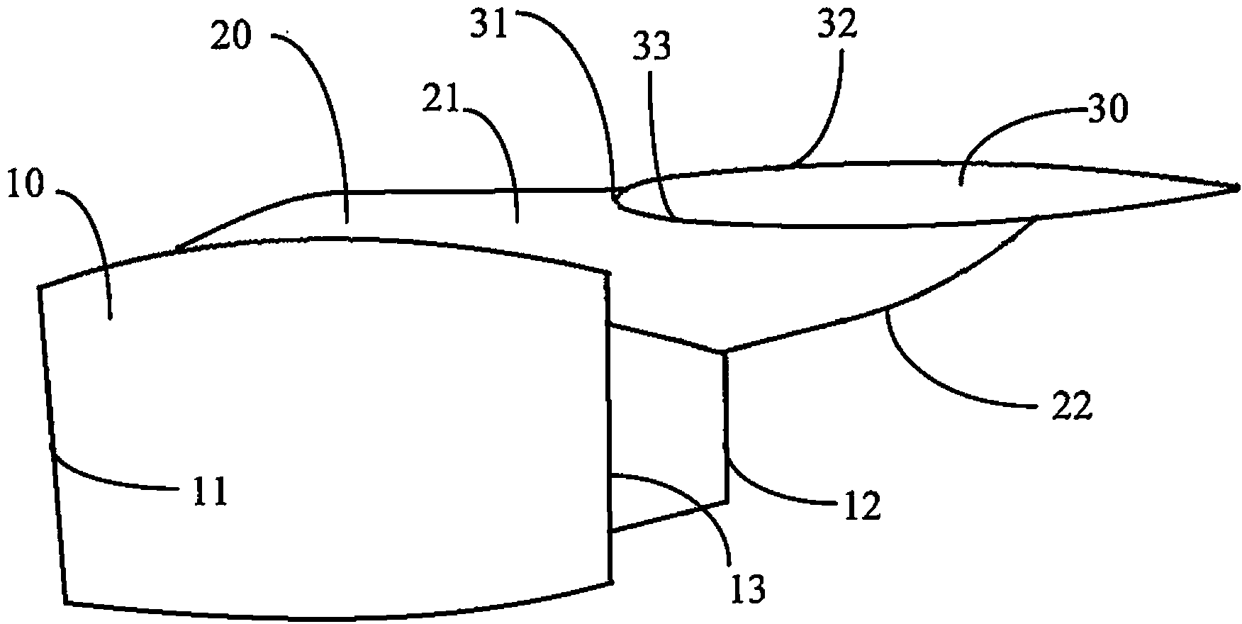
[0020] The structure of the fairing suspended in the aircraft with wing suspension layout according to the present invention will be specifically described below. In the following detailed description, directional terms, such as up, down, left, right, etc., are used with reference to the directions described in the drawings, and these directional terms are only for illustration rather than limitation. The exemplary structural design drawings and the following description of the embodiments of the present invention combined are not intended to exhaust all embodiments according to the present invention.

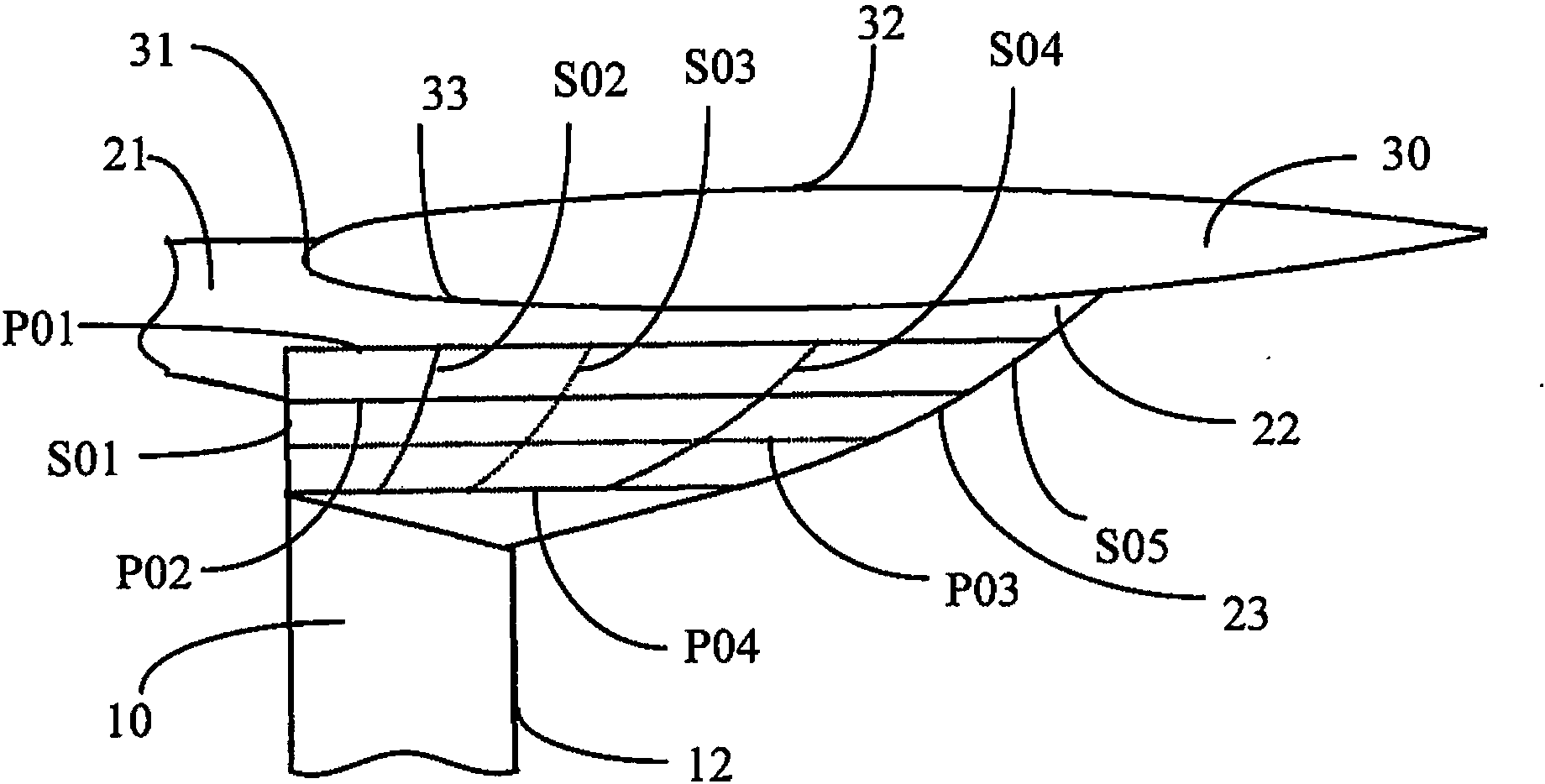
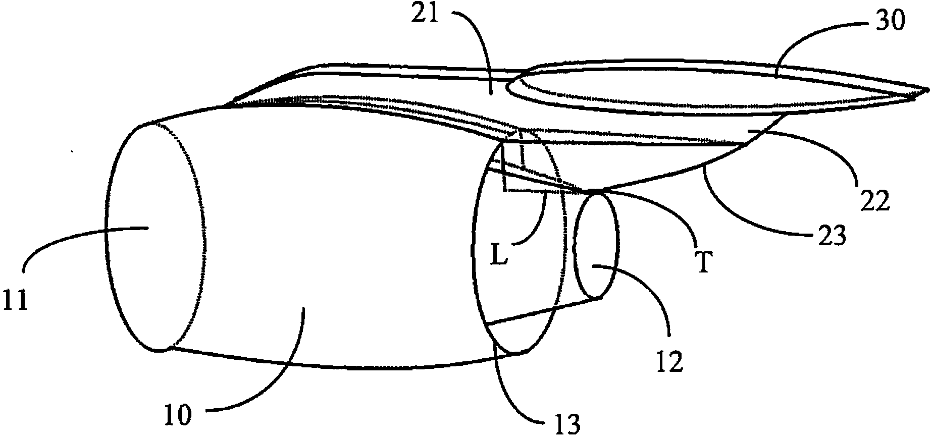
[0021] combine figure 1 and figure 2 As shown, in a preferred embodiment of the present invention, the improved design of the suspended fairing structure is realized by modeling at least a part of the suspended rear fairing using section control lines. For those skilled in the art, the modeling and shaping technology should be well known, and will not be repeated here. Wher...


PUM


Abstract

The invention provides a fairing structure for a pylon (20) of an aircraft with wing-mounted layout. The fairing structure comprises a front fairing (21) located in front of a wing leading edge (31) and a rear fairing (22) located behind the wing leading edge (31). The fairing structure is characterized in that at least part of the rear fairing (22) is realized by cross section control line modeling forming, and comprises at least one group of horizontal position control lines (P01, P02, P03, P04) and at least one group of longitudinal position control lines (S01, S02, S03, S04, S05). Through formation of the rear fairing of the pylon by the horizontal and longitudinal position control lines, the invention can conduct pylon design only through curvature control on the rear fairing of the pylon, and can realize optimization on flow area among the pylon / wing / engine nacelle without deflection on the rear portion of the pylon.

Description

technical field [0001] The present invention generally relates to the field of aircraft aerodynamic shape design, and more specifically relates to a fairing structure suspended in an aircraft with a wing suspension layout, especially a rear fairing structure. Background technique [0002] During the flight of the aircraft, both the upper surface and the lower surface of the wing generate lift. Generally, during cruising flight, it is necessary to ensure that the upper and lower surfaces of the wing do not generate air separation. For the aircraft with the engine installed under the wing (wing suspension layout aircraft), the upper surface of the wing generally has no large protruding parts, while the lower surface of the wing is in contact with the engine suspension, and the lower surface of the wing is easily rectified by the suspension. The influence of the airflow around the aerodynamic surface of the hood. If the lower surface of the wing is greatly adversely affected b...

Claims


Application Information

Patent Timeline
Patent Type & Authority Applications(China)
IPC IPC(8): B64C7/02B64D29/02
CPCB64C23/00B64D27/00B64D29/02Y02T50/40B64C1/40B64C7/02
Inventor 陈迎春张淼于哲慧张美红薛飞刘铁军张冬云周峰马涂亮赵宾宾
Owner COMAC
Learn More