Network type seepage discharging device in transverse direction, longitudinal direction and vertical direction

A network-type, vertical technology, applied in the direction of water supply equipment, sewage discharge, waterway system, etc., can solve the problems of ineffective line effect, limited range of hydraulic influence, frequent fluctuation of infiltration line, etc., so as to reduce the infiltration line and air resistance The effect of small size and easy maintenance

Inactive Publication Date: 2014-03-05
CHANGSHA DESIGN & RES INST OF CHEM IND MIN
View PDF6 Cites 15 Cited by
  • Summary
  • Abstract
  • Description
  • Claims
  • Application Information

AI Technical Summary

Problems solved by technology

[0004] At present, the common horizontal seepage drainage system has a small water head difference between collecting and transporting seepage water, and the range of hydraulic influence is limited, so the effect of reducing the infiltration line is not obvious. Vertical seepage drainage often requires the use of machinery and long-term power consumption, resulting in fluctuations in the infiltration line Frequent, complex equipment maintenance

Method used


Image

  • Network type seepage discharging device in transverse direction, longitudinal direction and vertical direction
  • Network type seepage discharging device in transverse direction, longitudinal direction and vertical direction
  • Network type seepage discharging device in transverse direction, longitudinal direction and vertical direction

Examples


Embodiment Construction

[0030] The present invention will be further described below in conjunction with embodiment and accompanying drawing.

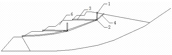
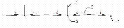
[0031] Referring to the accompanying drawings, this embodiment includes a vertical seepage collection body 1, a horizontal and horizontal seepage collection body 2, a horizontal and vertical drainage pipe 3, and a longitudinal flow guide pipe 4;

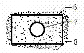
[0032] The horizontal lateral seepage collection body 2 is on the slope of the sedimentary shoal at the design elevation and the design distance from the outer edge of the accumulation dam crest (the accumulation dam crest refers to the last stage of the accumulation dam at a certain moment. The location of the crest, whose elevation is the highest elevation of the accumulation dam at a certain moment), when the surface of the sedimentary shoal of the accumulation dam body 6 can stand people, excavate a trench parallel to the axis of the accumulation dam body, and the cross-sectional shape of the trench is rectangula...


PUM


Abstract

The invention discloses a network type seepage discharging device in the transverse direction, the longitudinal direction and the vertical direction. The network type seepage discharging device comprises vertical seepage collecting bodies, a horizontal transverse seepage collecting body, horizontal longitudinal seepage discharging pipes and a longitudinal flow guiding pipe. A seepage discharging structure of a single node is composed of each vertical seepage collecting body and the corresponding horizontal longitudinal seepage discharging pipe; the horizontal transverse seepage collecting body is connected with the seepage discharging structures of the nodes in the same layer in series, so that a linear seepage discharging structure of each elevation is formed; the linear seepage discharging structures of the elevations are connected in series through the longitudinal flow guiding pipe, so that the network type seepage discharging device is formed in the transverse direction, the longitudinal direction and the vertical direction. According to the network type seepage discharging device in the transverse direction, the longitudinal direction and the vertical direction, seepage discharging is conducted in a combined mode in three directions, a combined type automatically-flowing seepage discharging whole body is formed, the air resistance is small, the seepage permeability is good, washing and dredging are convenient, following maintenance is convenient, the network type seepage discharging device in the transverse direction, the longitudinal direction and the vertical direction is economical, durable, suitable for various solid waste field accumulation bodies of upstream damming and capable of achieving the purpose of effective reduction of an accumulation body seepage line and guaranteeing the operation safety of a dam.

Description

technical field [0001] The invention relates to a combined seepage drainage device for reducing the infiltration line of accumulation bodies in the later stage of solid waste yards, in particular to a horizontal, vertical and vertical three-way network drainage for tailings dams, red mud dams, ash dams and other dams device. Background technique [0002] my country is a big mining country, and most of the tailings produced in the process of mine production and processing are discharged into tailings ponds for storage. At present, my country's tailings reserves exceed 10 billion tons, and 800-100 million tons of tailings are added every year. By the end of 2008, there were 12,655 tailings ponds nationwide, and 300 new tailings were added every year. Tailings ponds are one of the major hazards. Among the major disasters in the world, tailings pond disasters rank 18th after earthquakes, cholera, floods and hydrogen bombs. Therefore, the safety and stability of the tailings po...

Claims


Application Information

Patent Timeline
Patent Type & Authority Applications(China)
IPC IPC(8): E03F1/00E02D3/10
Inventor 陈雯邓书申唐猛彭珂
Owner CHANGSHA DESIGN & RES INST OF CHEM IND MIN
Why Eureka
Try Eureka