
Centering device for drill rod in hole of engineering driller

A technology for engineering drilling rigs and inner drill pipes, which is applied in the direction of drill pipes, drill pipes, drilling equipment, etc. It can solve the problems of reducing torque and damage to the hole wall, and achieve the effects of reducing torque, reducing damage to the hole wall, and reducing severe vibration

Active Publication Date: 2014-03-05
CHONGQING EXPLORATION MACHINER FACTORY
View PDF5 Cites 4 Cited by
  • Summary
  • Abstract
  • Description
  • Claims
  • Application Information

AI Technical Summary

Problems solved by technology

However, it is difficult for the centralizers in the prior art to reduce the torque and not generate relative rotational movement with the inner wall of the hole, which causes great damage to the hole wall

Method used


Image

  • Centering device for drill rod in hole of engineering driller
  • Centering device for drill rod in hole of engineering driller
  • Centering device for drill rod in hole of engineering driller

Examples


Embodiment Construction

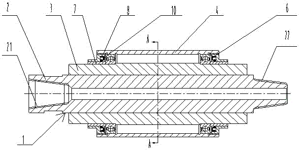
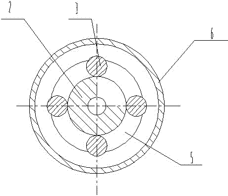
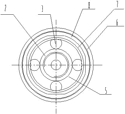
[0021] Such as figure 1 , 2 As shown in , 3, the centralizer used for the drill pipe in the engineering drilling rig hole of the present invention includes a body 1, and the body 1 mainly includes a mandrel 2, a rib 3 and an outer shell 4, the mandrel 2 is located at the center, and its The two ends are respectively provided with a tapered internal thread 21 and a tapered external thread 22. During use, the tapered internal thread 21 and the tapered external thread 22 at both ends are respectively connected with the threaded ends (male end, female end) of the drill rod in the hole. head) is connected by tightening to form the drill string to transmit motion and torque; the middle of the mandrel 2 is hollow to form a passage for the mud, water or gas required for drilling; the ribs 3 are two or more, uniform It is arranged on the outer surface of the mandrel 2, that is, evenly arranged along the circumferential direction. The ribs 3 can be two, three, four, five, six, eight or...


PUM


Abstract

The invention discloses a centering device for a drill rod in a hole of an engineering driller. The centering device comprises a central spindle, ribs and an outer shell. The hollow central spindle is located at the center, wherein the two ends of the central spindle are provided with a conical internal thread and a conical external thread respectively. The number of the ribs is two or more, and the ribs are evenly arranged on the outer surface of the central spindle to be firmly connected with the central spindle. A gap is reserved between every two adjacent ribs to form a through groove. The two ends of the outer shell are respectively provided with a rolling bearing, wherein the inner side of the rolling bearing is arranged on the outer surface each rib in a supporting mode, the outer side of the rolling bearing is in close fit with the inner surface of the outer shell, and the ribs and the outer shell rotate relative to each other through the rolling bearing. The centering device can keep the thin and long drill rod running stably, make the axis of a drill bit be close to the center line of the drilled hole as much as possible, effectively prevent the hole from inclining, mitigate violent vibration of a drill rod elastic system in the hole in the radial direction and in the axial direction, and reduce deflecting friction between the drill rod and the drill bit; besides, the drill rod does not make direct contact with the wall of the hole so that damage to the wall of the hole can be reduced effectively, and torque required for drilling is reduced.

Description

technical field [0001] The invention relates to an accessory part of an engineering drilling rig, in particular to a centralizer used for drilling rods in holes of the engineering drilling rig. [0002] technical background [0003] As a mechanical device for drilling, the engineering drilling rig drives the drill pipe (active drill pipe, drill pipe in the hole) to rotate through the power head, and pushes the power head to move down to generate drilling force and drill holes of the required size. When the inner diameter of the drilled hole is small, the inner diameter of the drill pipe in the hole is basically the same as that of the hole; if the drill pipe in the hole vibrates in the radial and axial directions, it is easy to contact the inner wall of the hole. There is a certain damage to the inner wall of the hole, which will cause the hole to collapse in severe cases; secondly, more torque is consumed, more energy is required, or a larger type of drill is required ...

Claims


Application Information

Patent Timeline
Patent Type & Authority Applications(China)
IPC IPC(8): E21B17/10
Inventor 田虎褚明唐健
Owner CHONGQING EXPLORATION MACHINER FACTORY
Learn More