Cylinder cover with shielding wall structure, manufacturing method and engine

A technology of shielding wall and cylinder head, applied in engine components, combustion engines, machines/engines, etc., can solve the problems of exhaust gas, unable to meet the needs of tumble flow and combustion, unable to meet the needs of gasoline engine use, etc. The effect of flow ratio

Active Publication Date: 2014-03-05
ANHUI JIANGHUAI AUTOMOBILE GRP CORP LTD
View PDF6 Cites 7 Cited by
  • Summary
  • Abstract
  • Description
  • Claims
  • Application Information

AI Technical Summary

Problems solved by technology

However, the air intake shielding wall in a two-stroke diesel engine cannot be directly applied to a gasoline engine. The problem is: 1. The above-mentioned shielding wall is applied to a two-stroke diesel engine, and the number of strokes is not the same. When the compression piston moves upward, the exhaust valve is still open to sweep the exhaust gas in the cylinder, which improves the ability to sweep exhaust gas. Then, the four-stroke gasoline engine has already closed the exhaust valve when the piston moves upward, so it is impossible to use the piston to move upward to compress the combustible mixture to discharge the exhaust gas; 2. Gasoline engine and diesel engine have different main movement patterns of gas in the cylinder. Diesel engine mainly uses complex intake manifold to sacrifice kinetic energy to improve gas swirl flow. Gasoline engine air passage is mainly straight tangential air passage with low resistance, and air intake depends on cylinder The movement of the wall and the piston

Method used


Image

  • Cylinder cover with shielding wall structure, manufacturing method and engine
  • Cylinder cover with shielding wall structure, manufacturing method and engine
  • Cylinder cover with shielding wall structure, manufacturing method and engine

Examples


Embodiment Construction

[0029] The technical solution of the present invention will be described in detail below through the examples. It should be understood that the following examples are exemplary only, and can only be used to explain and illustrate the technical solution of the present invention, and cannot be interpreted as the technical solution of the present invention. limits.

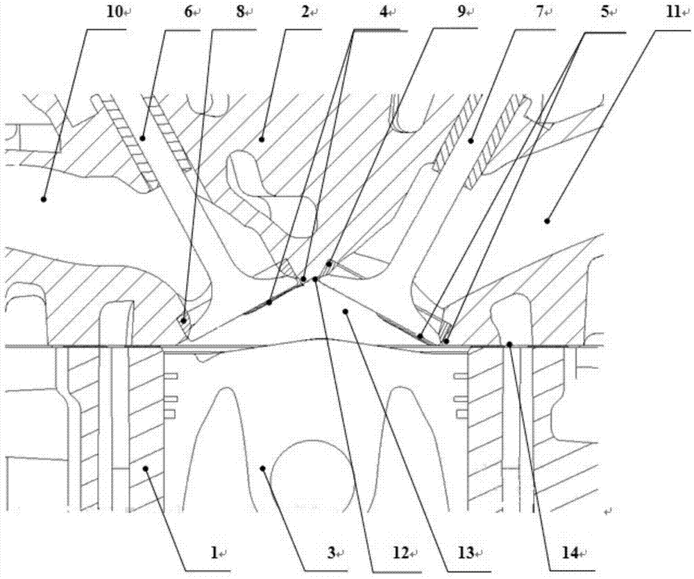
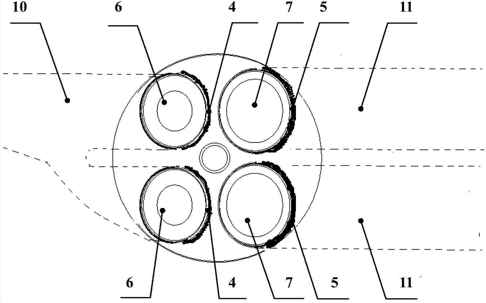
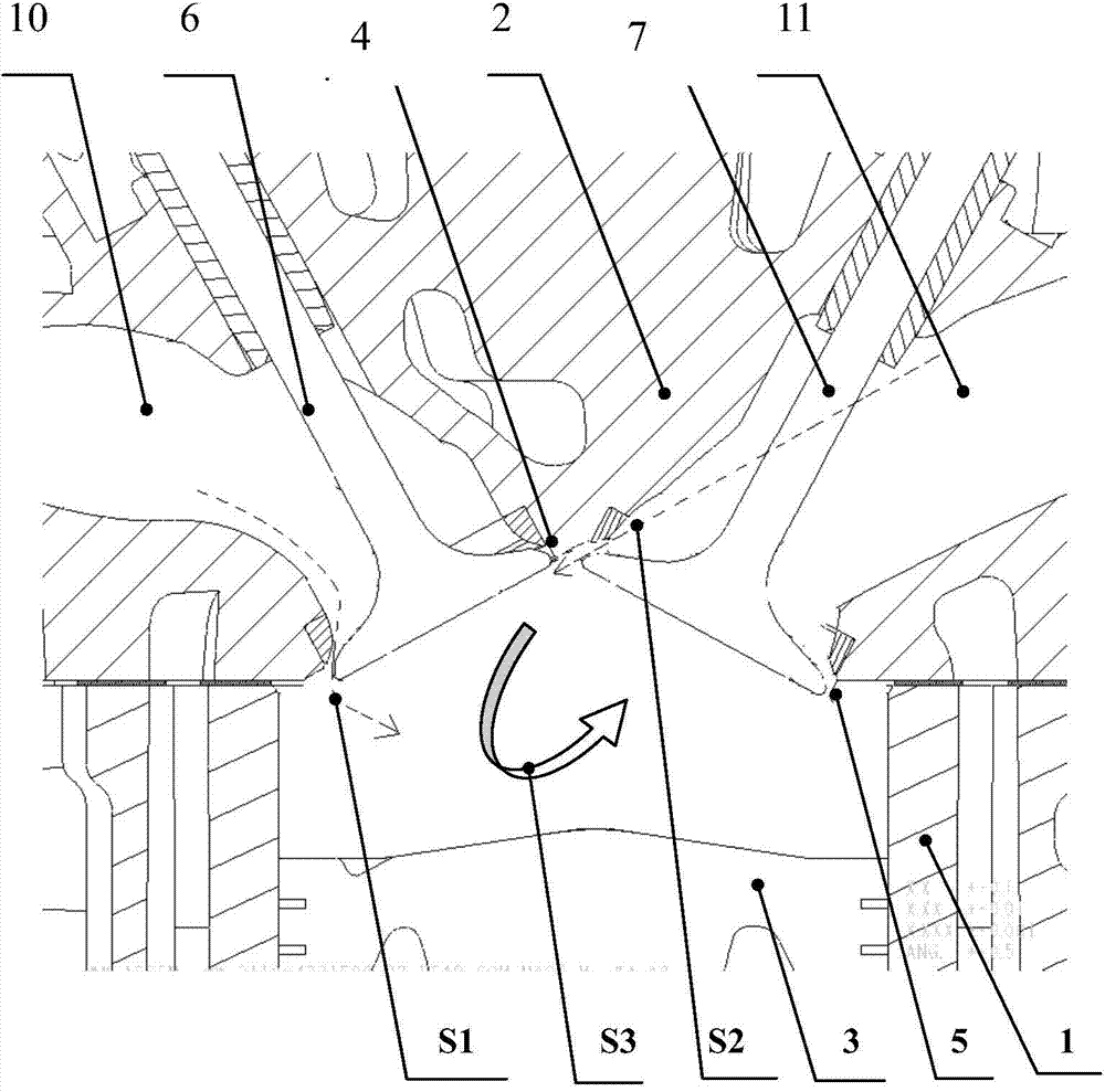
[0030] see figure 1 and figure 2 , the engine cylinder block 1, the piston 3 can reciprocate up and down in the cylinder block 1, the cylinder head 2 is installed on the cylinder block 1 through the seal of the cylinder gasket 14, and the combustion chamber 13 is composed of the cylinder head inner wall 12 of the cylinder head 2 and the piston 3 The upper surface is composed together. The exhaust valve seat 8 and the intake valve seat 9 are respectively press-fitted on the cylinder head 2, and then machined to form good sealing surfaces with the exhaust valve 6 and intake valve 7 respectively. The air channel 10 ...


PUM


Abstract

The invention relates to a cylinder cover with a shielding wall structure. The cylinder cover comprises a cylinder cover base body, an exhaust valve seat ring and an intake valve seat ring, wherein the exhaust valve seat ring and the intake valve seat ring are installed on a cylinder cover body in a pressed mode. The cylinder cover further comprises an exhaust valve, an intake valve, an exhaust passage, an intake passage, a cylinder cover inner wall, an exhaust shielding wall arranged on the periphery of the exhaust valve, and an intake shielding wall arranged on the periphery of the intake valve. By means of the technical scheme, the combustor cylinder cover with a new intake-exhaust shielding wall structure is fully capable of being provided to improve the intake rolling flow rate of a four-stroke internal combustion engine, the EGR capacity inside a cylinder when loads are low, and the efficient backflow gas changing exhaust gas sweeping capacity when the loads are high, the combustion quality of the engine is improved, and the power and the economical efficiency are improved.

Description

technical field [0001] The invention belongs to the technical field of internal combustion engines, and in particular relates to an engine with a shielding wall structure for a cylinder head intake valve and an exhaust valve of a combustion chamber and a preparation method thereof. Background technique [0002] In the development of engine products, it is hoped that the developed engine will have good power and economy, and at the same time, in order to meet the increasingly stringent emission regulations, it needs to have better emission performance. However, the reasonable matching of the combustion system, the structure of the combustion chamber, Proper air movement has a big impact on these properties. In this regard, the valve shielding wall can be added through the design of the combustion chamber structure to improve the rationality of the airflow movement and achieve better combustion quality. When the valves are overlapped and opened, it is not expected that the fre...

Claims


Application Information

Patent Timeline
IPC IPC(8): F02F1/24B23P15/00
CPCY02T10/12
Inventor 阮仁宇李龙超杜鹏田国庆许涛滕建耐张增光张良超侯亦波路明
Owner ANHUI JIANGHUAI AUTOMOBILE GRP CORP LTD
Why Eureka
Try Eureka