Hydraulic control system for cage supporting and locking device

A technology of hydraulic control system and tank lock, which is applied in the direction of fluid pressure actuation system components, fluid pressure actuation devices, mechanical equipment, etc. It can solve the problems of low degree of automation and inconvenient cooling of hydraulic oil, and achieve the effect of automatic cooling

Inactive Publication Date: 2014-03-05
徐州泰荣煤矿设备有限公司
View PDF0 Cites 0 Cited by
  • Summary
  • Abstract
  • Description
  • Claims
  • Application Information

AI Technical Summary

Problems solved by technology

[0003] In order to solve the problems of low automation and inconvenient cooling of hydraulic oil in the existing hydraulic control system, the present invention provides a hydraulic control system for tank holding and locking device, The hydraulic control system can realize automatic oil injection and automatic cooling, and can display the status of the tank support and lock tank in real time, which brings great convenience to mine construction

Method used


Image

  • Hydraulic control system for cage supporting and locking device

Examples


Embodiment Construction

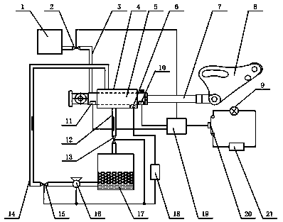
[0009] In the figure, the hydraulic control system for the tank holder lock device includes an oil storage tank 1, an oil supply solenoid valve 2, an oil supply pipe 3, a cooling chamber 4, a temperature sensor 6, an indicator light 9, an oil pressure sensor 10 in the front cavity, and a rear cavity oil pressure sensor 10. Cavity oil pressure sensor 11, return water pipe 12, return water solenoid valve 13, water supply pipe 14, water supply solenoid valve 15, water pump 16, cooling water tank 17, cooling controller 18, comparison controller 19, electromagnetic switch 20 and battery 21; The outside of the oil cylinder 5 of the tank lock device is provided with a cooling chamber 4, the lower part of the cooling chamber 4 communicates with the upper part of the cooling water tank 17 through the return pipe 12, the return water pipe 12 is provided with a return solenoid valve 13, and the lower side of the cooling water tank The water supply pipe 14 communicates with the top of th...


PUM


Abstract

The invention relates to a hydraulic control system for a cage supporting and locking device. A cooling chamber is arranged outside an oil cylinder of the cage supporting and locking device. The cooling chamber is communicated with a cooling water tank through a water return pipe. The side face of the lower portion of the cooling water tank is communicated with the upper portion of the cooling chamber through a water supply pipe. A temperature sensor is arranged on the inner wall of the cooling chamber. The temperature sensor is electrically connected with the input end of a cooling controller through a wire. The output end of the cooling controller is simultaneously and electrically connected with a water supply electromagnetic valve, a water pump and a water return electromagnetic valve. A front-cavity oil pressure sensor and a rear-cavity oil pressure sensor are connected with two input ends of a comparison controller respectively. An output end I of the comparison controller is electrically connected with an electromagnetic switch. An output end II of the comparison controller is electrically connected with an oil supply electromagnetic valve which is located on an oil supply pipe. By the adoption of the hydraulic control system for the cage supporting and locking device, automatic oil injection and automatic cooling can be achieved, the cage supporting and locking state can be displayed in real time, and mine construction is greatly facilitated.

Description

technical field [0001] The invention relates to a hydraulic control system, in particular to a hydraulic control system for a tank holding and locking device which can realize automatic control. Background technique [0002] At present, the hydraulic control system used in the support tank lock device cannot sense the state of the support tank lock at any time, and the cooling of the hydraulic oil is inconvenient. If the temperature of the hydraulic oil rises to a certain value, it will cause serious safety hazards and even cause explosions. Affected mine construction. Contents of the invention [0003] In order to solve the problems of low automation and inconvenient cooling of the hydraulic oil in the existing hydraulic control system, the present invention provides a hydraulic control system for a tank holding and locking device. The hydraulic control system can realize automatic oil filling, automatic cooling, and real-time The accurate display of the status of the ta...

Claims


Application Information

Patent Timeline
Patent Type & Authority Applications(China)
IPC IPC(8): F15B21/04F15B21/02
Inventor 朱苏辉杨建奎王雷陈义强李祝民王威风鲁海涛王善新张爱萍李晓刚权启栋刘跃郝远明王海峰
Owner 徐州泰荣煤矿设备有限公司
Why Eureka
Try Eureka