Centrifugal electromagnetic clutch and water pump with centrifugal electromagnetic clutch

An electromagnetic clutch and centrifugal clutch technology, applied in the direction of magnetic drive clutches, clutches, non-mechanical drive clutches, etc., can solve the problems of unfavorable automobile energy saving and emission reduction and environmental protection, increase of automobile fuel consumption and emissions, and increase of automobile engine load, etc., to achieve reduction The effect of pump failure probability, compact structure, and distance reduction

Active Publication Date: 2014-03-05
LONGKOU ZHONGYU MACHINERY
View PDF10 Cites 10 Cited by
  • Summary
  • Abstract
  • Description
  • Claims
  • Application Information

AI Technical Summary

Problems solved by technology

[0003] The traditional automobile water pump has no clutch control. As long as the engine is running, the water pump will work, which will increase the load on the automobile engine, increase the fuel consumption and emission of the automobile, and is not conducive to automobile energy saving, emission reduction and environmental protection. Some automobile water pumps use traditional electromagnetic clutch control switches. The instantaneous impact force is large, which may easily cause the impeller of the water pump to fall off, and because the traditional electromagnetic clutch is large in size, it requires a large installation space and occupies an additional assembly space of the water pump

Method used


Image

  • Centrifugal electromagnetic clutch and water pump with centrifugal electromagnetic clutch
  • Centrifugal electromagnetic clutch and water pump with centrifugal electromagnetic clutch
  • Centrifugal electromagnetic clutch and water pump with centrifugal electromagnetic clutch

Examples


Embodiment Construction

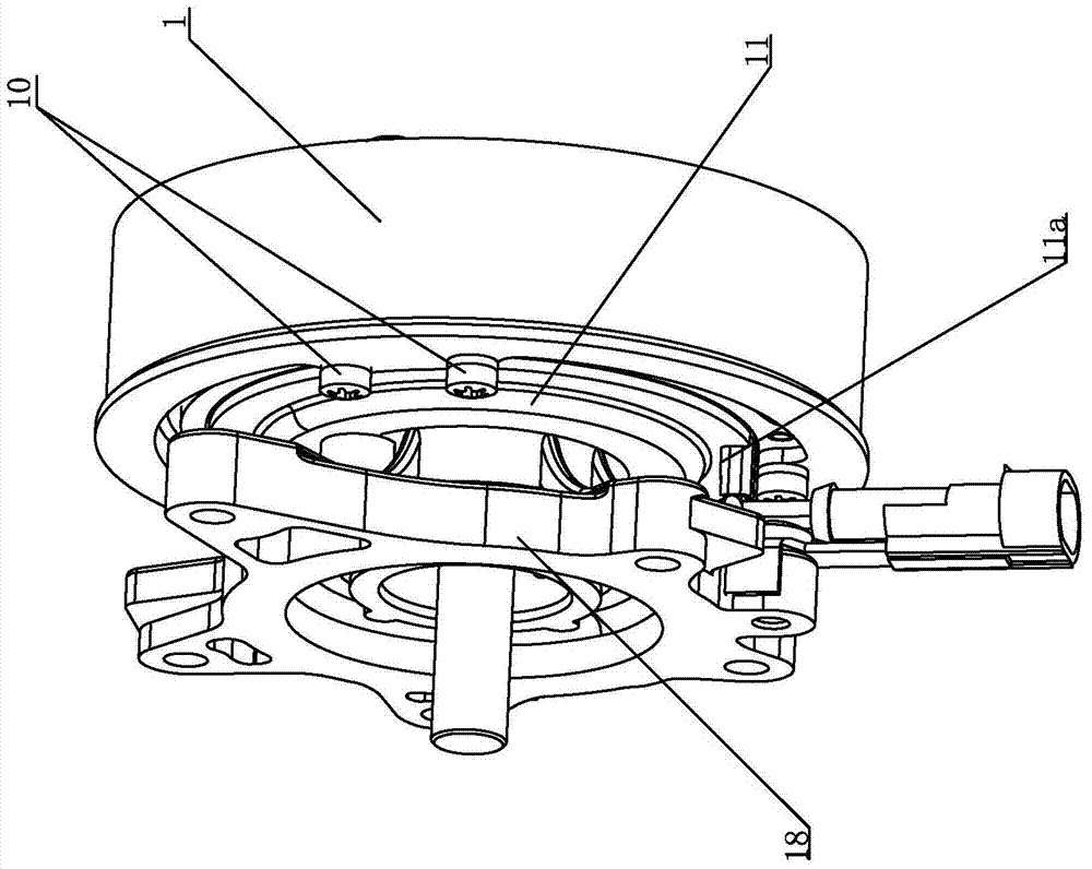
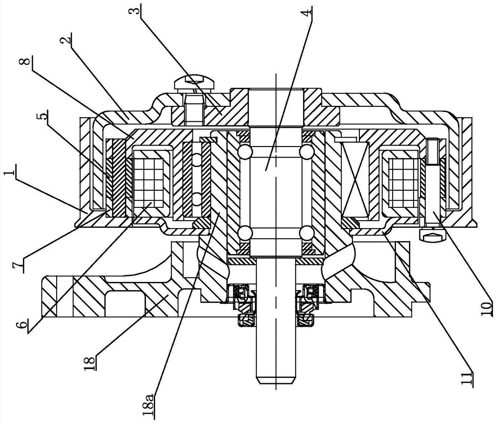
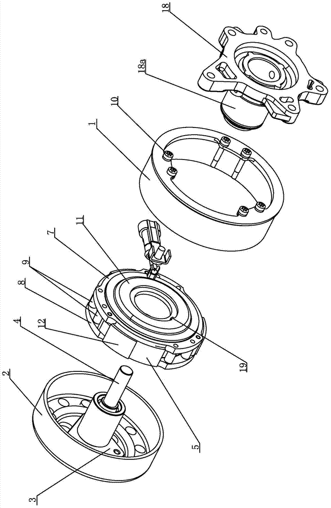
[0024] figure 1 , 2 , 3, 4 show the one-speed structure of the centrifugal electromagnetic clutch of the present invention, as figure 1 , 2 As shown, it includes: the first rotating body 1 is driven to rotate by the engine; the second rotating body 2 is fixedly connected with the transmission shaft 4 through the flange 3, and the second rotating body 2 is radially located at the center of the first rotating body 1 Inside: The centrifugal clutch device that transmits the power of the first rotating body 1 to the second rotating body 2 is located between the first and second rotating bodies in the axial direction and inside the second rotating body 2 in the radial direction.

[0025] like image 3 , 4 As shown, the centrifugal clutch device includes: 3 magnetically conductive centrifugal pieces 5 (the number of magnetically conductive centrifugal pieces can be set according to needs, and 3 are preferably set in this embodiment), an electromagnetic coil 6 for attracting magne...


PUM


Abstract

Provided is a centrifugal electromagnetic clutch. The centrifugal electromagnetic clutch comprises a first rotating body, a second rotating body and a transmission shaft, wherein the second rotating body can rotate along with the first rotating body, power of the second rotating body is transmitted out through the transmission shaft, the second rotating body is arranged inside the first rotating body in a radial mode, and a centrifugal clutch device is axially arranged between the first rotation body and the second rotating body, and is arranged inside the second rotating body in a radial mode. The centrifugal clutch device comprises a plurality of magnetism-conductive centrifugal pieces, an electromagnetic coil, a magnetism-conductive connecting body and a magnetism-conductive supporting body, wherein the magnetism-conductive connecting body is fixed to the inner side of the first rotating body, and is arranged outside the electromagnetic coil in a radial mode, the magnetism-conductive supporting body is installed on the transmission shaft, the first rotating body is fixed to the magnetism-conductive supporting body, the magnetism-conductive centrifugal pieces are distributed along the outer circumference of the electromagnetic coil, one end of each magnetism-conductive centrifugal piece is hinged to the position between the magnetism-conductive connecting body and the magnetism-conductive supporting body, friction plates are arranged on the outer surfaces of the magnetism-conductive centrifugal pieces, wear-resistant layers are arranged on the inner wall face, opposite to the friction plates, of the second rotating body, when the electromagnetic coil is deenergized, the friction plates are attached to the wear-resistant layers of the second rotating body, and when the electromagnetic coil is energized, the friction plates are separated from the wear-resistant layers of the second rotating body.

Description

technical field [0001] The invention relates to an electromagnetic clutch, in particular to a centrifugal electromagnetic clutch used for controlling the switch of an automobile water pump. Background technique [0002] The clutch of the electromagnetic clutch realizes the attraction and separation with other magnetic components by controlling the power on and off of the electromagnetic coil. The action of the traditional electromagnetic clutch is along the axis of the main shaft, and the coil of the electromagnetic core can be attracted by it. The magnetically conductive parts and other driven components connected to the magnetically conductive parts are arranged and installed along the axis of the main shaft, which makes the overall volume of the clutch larger and occupies a larger installation space. [0003] The traditional automobile water pump has no clutch control. As long as the engine is running, the water pump will work, which will increase the load on the automobi...

Claims


Application Information

Patent Timeline
Patent Type & Authority Applications(China)
IPC IPC(8): F16D27/102F04D13/02F04D15/00
Inventor 王兆宇邢子义
Owner LONGKOU ZHONGYU MACHINERY
Why Eureka
Try Eureka