Electromagnetic valve resistant to oil pollution

A solenoid valve and anti-oil pollution technology, applied in the field of solenoid valve, can solve problems such as endangering the safe and stable operation of the unit, affecting the normal operation of the speed control system, affecting the working performance of the solenoid valve, etc., achieving simple structure, strong anti-pollution ability, and integration. high effect

Active Publication Date: 2014-03-05
CHINA YANGTZE POWER
View PDF5 Cites 2 Cited by
  • Summary
  • Abstract
  • Description
  • Claims
  • Application Information

AI Technical Summary

Problems solved by technology

[0002] The existing ordinary solenoid valves have high quality requirements for hydraulic oil, especially the solid particles contained in the oil directly affect the working performance of the solenoid valve, causing the solenoid valve core to jam and refuse to move.
[0003] The turbine oil system of a hydropower station is usually composed of a speed control system oil system and a bearing lubricating oil system. Due to the friction of the bearing system and the contact between the lubricating oil and the air, there are many solid particles and sludge in the oil. Normal operation in such an environment with severe oil pollution
If the overspeed protection solenoid valve of the hydropower unit is stuck astringent , Refusal to move, it will affect the normal operation of the speed control system, and even endanger the safe and stable operation of the entire unit

Method used


Image

  • Electromagnetic valve resistant to oil pollution

Examples


Embodiment Construction

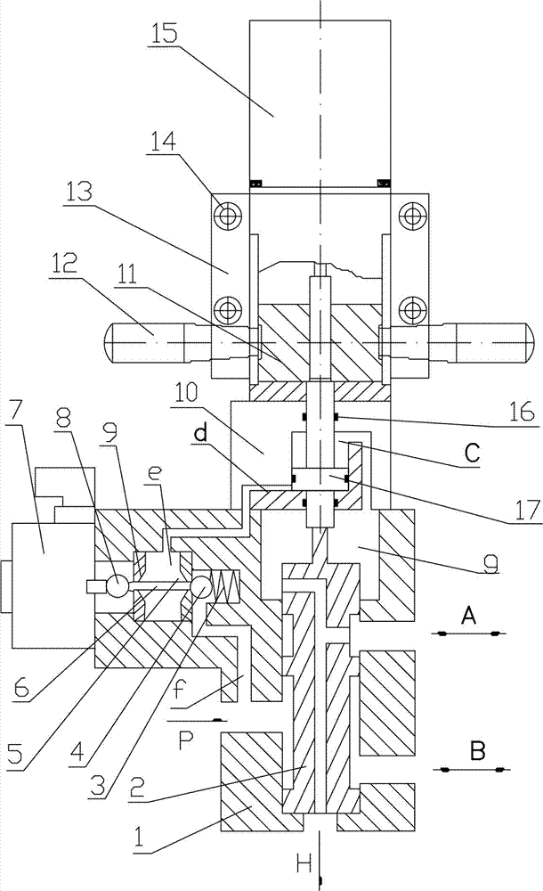
[0014] See attached figure 1 As shown, an anti-oil pollution solenoid valve includes a valve body 1, a valve core 2, a spring 3, a first steel ball 4, a first valve 5, a connecting rod 6, a first electromagnet 7, a second steel ball 8, The second valve 9, housing 10, counterweight 11, bracket 13, second electromagnet 15 and piston 17, the second electromagnet is vertically installed on the bracket, the bracket is installed on the top of the housing, and the valve body is installed on the top of the housing. In the lower part, the bracket has an inner hole, and the counterweight is installed in the inner hole of the bracket, and can move vertically in the hole; the first electromagnet is installed and fixed on the side of the valve body; a piston is installed in the housing, and the upper and lower ends of the piston are provided with Piston rod; the lower end of the iron core of the second electromagnet is connected with the piston rod on the upper part of the piston. The mo...


PUM


Abstract

An electromagnetic valve resistant to oil pollution comprises a valve body, a first steel ball, a first valve, a first electromagnet, a second steel ball, a second valve, a second electromagnet and the like, wherein the second electromagnet is vertically installed on a support, the support is installed on the upper portion of a shell body, the valve body is installed on the lower portion of the shell body, the support is provided with an inner hole, and a balance weight is installed in the inner hole of the support and can vertically move in the hole; the first electromagnet is installed and fixed to the side portion of the valve body; a piston is installed in the shell body, and piston rods are installed at the upper end and the lower end of the piston; the lower end of an iron core of the second electromagnet is connected together with the piston rod on the upper portion of the piston, the piston rod on the lower portion of the piston is installed in the central inner hole in the lower portion of the shell body, the lower end of the piston rod on the lower portion of the piston is connected together with the upper portion of a valve element, the piston in the shell body can move to drive the valve element and the balance weight to move at the same time, and the piston is installed in an inner cavity of the shell body. The electromagnetic valve has electromagnetic, hydraulic and manual multi-input control functions, is high in integration level and anti-pollution capacity, simple in structure and convenient to maintain, and can safely and reliably implement multi-mode combined control.

Description

technical field [0001] The invention belongs to the field of solenoid valves, in particular to an anti-oil pollution solenoid valve. Background technique [0002] The existing ordinary solenoid valves have high requirements on the quality of hydraulic oil, especially the solid particles contained in the oil directly affect the working performance of the solenoid valve, causing the solenoid valve core to jam and refuse to move. [0003] The turbine oil system of a hydropower station is usually composed of a speed control system oil system and a bearing lubricating oil system. Due to the friction of the bearing system and the contact between the lubricating oil and the air, there are many solid particles and sludge in the oil. Normal operation in such a heavily oil-polluted environment. If the overspeed protection solenoid valve of the hydropower unit is stuck astringent , Refusal to move, it will affect the normal operation of the speed control system, and even endanger the...

Claims


Application Information

Patent Timeline
Patent Type & Authority Applications(China)
IPC IPC(8): F16K11/065F16K31/06
CPCF16K11/22F16K31/061F16K31/122
Inventor 望勇郑健民刘旭垠陈阳陈宜黄明马龙周伍周小平潘峰
Owner CHINA YANGTZE POWER
Why Eureka
Try Eureka