Flywheel turbine

A flywheel and flywheel technology, applied in the field of flywheels, can solve the problems of complex equipment manufacturing, low injection speed, and low energy conversion rate, and achieve the effects of high energy utilization, improved power output, and sufficient fuel combustion

Inactive Publication Date: 2011-11-09
陈久斌
View PDF0 Cites 2 Cited by
  • Summary
  • Abstract
  • Description
  • Claims
  • Application Information

AI Technical Summary

Problems solved by technology

[0002] The existing thermal energy conversion method, the method of converting thermal energy into kinetic energy has a complex structure, too much energy loss caused by intermediate links and too low energy conversion rate, which makes equipment manufacturing very complicated, high equipment cost, low energy utilization rate, resulting in congenital Flaws in the theory of sexual design make it difficult to break through the technical bottleneck
The method of manufacturing high temperature and high pressure also has the problem of being unable to achieve higher temperature and pressure, making many materials impossible to produce
[0003] Existing engines mainly include internal combustion engines and jet engines. Intern

Method used


Image

  • Flywheel turbine
  • Flywheel turbine
  • Flywheel turbine

Examples


Example Embodiment

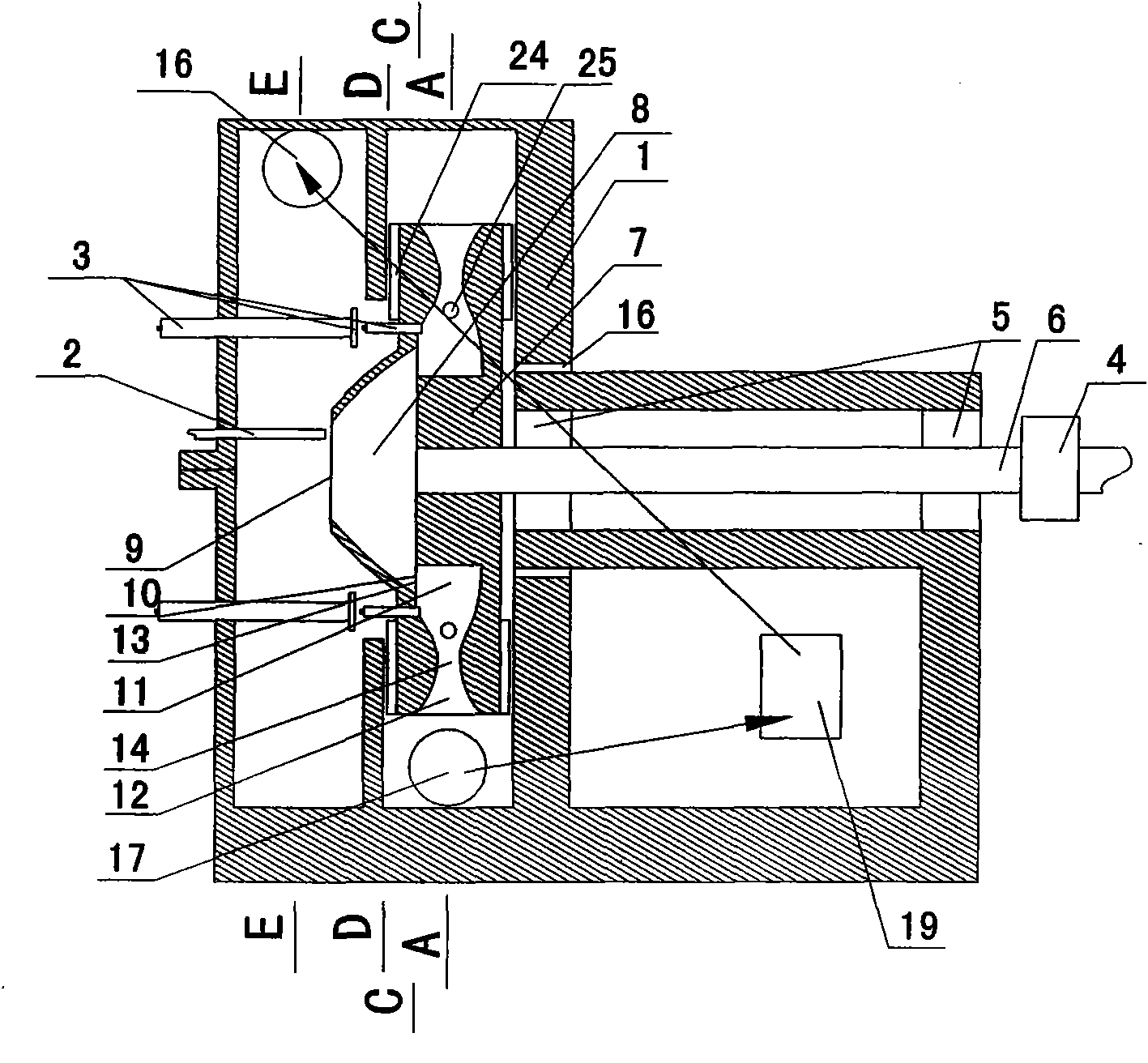
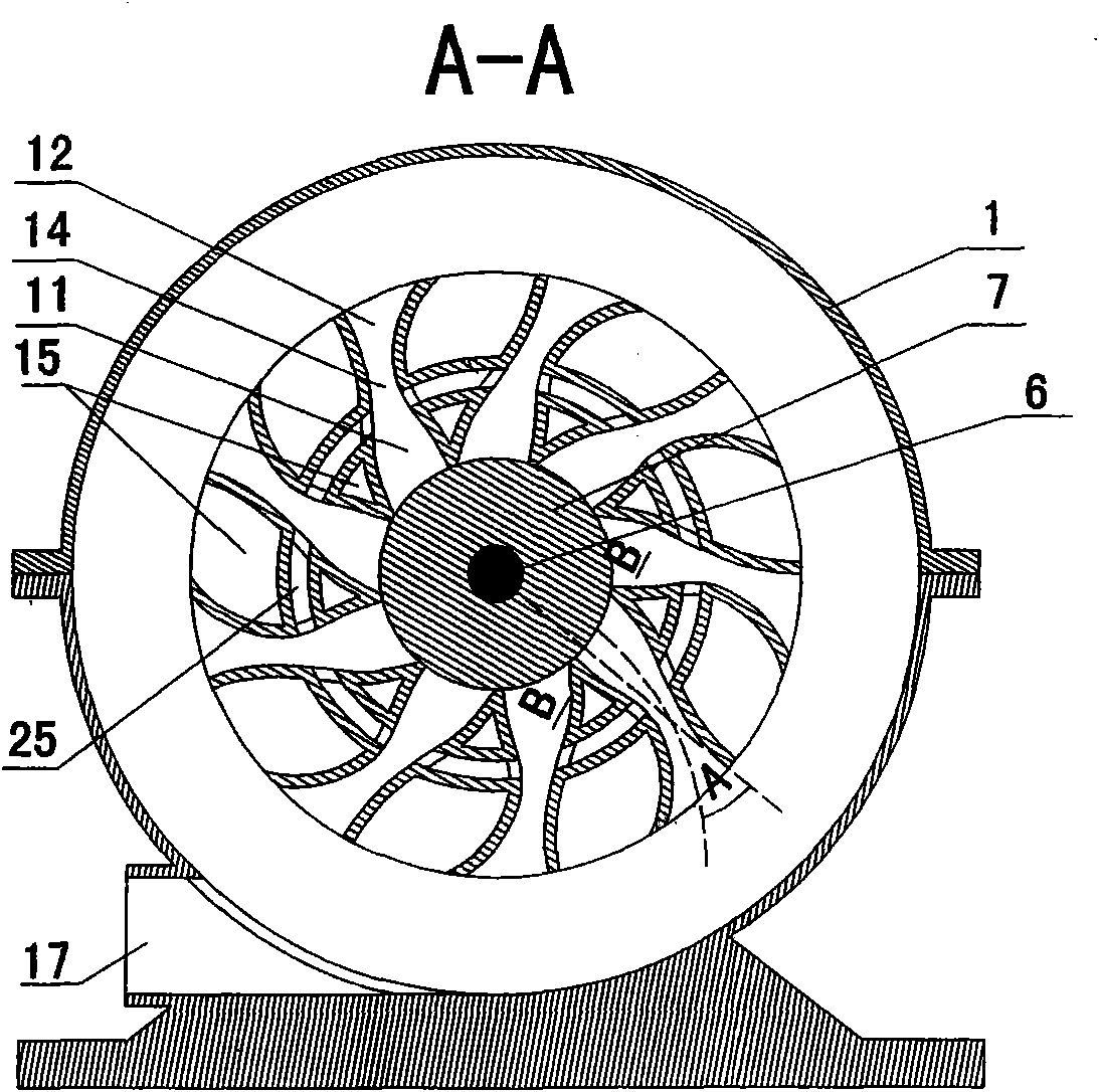
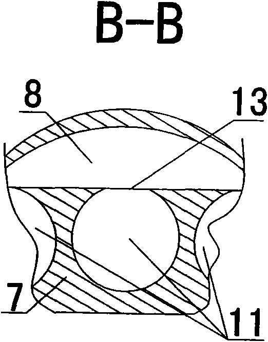
[0027] The main structure of the present invention is: the flywheel machine includes a housing 1, a fuel system 2, an ignition system 3, and a starting system 4. The housing 1 is equipped with a flywheel shaft 6 through a rotating device 5, and the flywheel shaft 6 is connected to the starting system 4. On the flywheel shaft 6 At least one flywheel 7 is installed, a gas mixing chamber 8 is arranged on the flywheel 7, the gas mixing chamber air inlet 9 is opened at the axial center of the gas mixing chamber 8, and the gas mixing chamber gas outlet 10 is arranged on the periphery of the gas mixing chamber 8, corresponding to the air inlet of the gas mixing chamber Port 9 is provided with fuel system 2, at least one combustion chamber 11 and jet chamber 12 are arranged on the periphery of flywheel 7, ignition system 3 is arranged corresponding to combustion chamber 11, combustion chamber 11 is provided with combustion chamber air inlet 13 and combustion chamber gas outlet 14, combu...


PUM


Abstract

The invention discloses a flywheel turbine which comprises a casing, a fuel system, an ignition system and a starting system, wherein the casing is provided with a flywheel shaft by a rotating device; the flywheel shaft is connected with the starting system; a flywheel is at least arranged on the flywheel shaft; a gas mixing chamber is arranged on the flywheel; a gas mixing chamber air inlet is arranged at the axial part of the gas mixing chamber; a gas mixing chamber air outlet is arranged on the periphery of the gas mixing chamber; the fuel system is arranged corresponding to the gas mixing chamber air inlet; a combustion chamber and a gas spraying chamber are at least arranged on the periphery of the flywheel; the ignition system is arranged corresponding to the combustion chamber which is provided with a combustion chamber air inlet and a combustion chamber air outlet; the combustion chamber air inlet is communicated with the gas mixing chamber air outlet; the combustion chamber air outlet is communicated with the gas spraying chamber; the area of the cross section of the combustion chamber air outlet is smaller than that of the maximum cross section of the combustion chamber; an inner cavity of the gas spraying chamber is expanded towards an opening in the direction of the outer edge of the flywheel; and an inclined angle is formed between the central axis of the gas spraying chamber and the radius of the flywheel. According to the flywheel turbine, by using the circular motion and the fluid motion, the fuel can be combusted more sufficiently, the energy can be converted more sufficiently and the structure is more simplified.

Description

technical field [0001] The invention relates to the fields of power equipment, engines and thermal equipment, in particular to a flywheel. Background technique [0002] The existing thermal energy conversion method, the method of converting thermal energy into kinetic energy has a complex structure, too much energy loss caused by intermediate links and too low energy conversion rate, which makes equipment manufacturing very complicated, high equipment cost, low energy utilization rate, resulting in congenital The flaws in the theory of sexual design make it difficult to break through the technical bottleneck. The method of manufacturing high temperature and high pressure also has the problem of not being able to achieve higher temperatures and pressures, making many materials impossible to produce. [0003] Existing engines mainly include internal combustion engines and jet engines. Internal combustion engines have fundamental defects such as large weight, low speed, high e...

Claims


Application Information

Patent Timeline
IPC IPC(8): F02K7/00F02G5/02
CPCY02T10/166Y02T10/12
Inventor 陈久斌
Owner 陈久斌
Why Eureka
Try Eureka